Coolant circuit of an internal combustion engine, and compensating vessel designed for said coolant circuit

A technology of balancing container and coolant, applied in the direction of engine cooling, machine/engine, mechanical equipment, etc., to avoid foaming and prevent vortex

Inactive Publication Date: 2014-09-24
VOLKSWAGEN AG
View PDF14 Cites 4 Cited by
  • Summary
  • Abstract
  • Description
  • Claims
  • Application Information

AI Technical Summary

Problems solved by technology

However, additional manufacturing effort is asso

Method used


Image

  • Coolant circuit of an internal combustion engine, and compensating vessel designed for said coolant circuit
  • Coolant circuit of an internal combustion engine, and compensating vessel designed for said coolant circuit
  • Coolant circuit of an internal combustion engine, and compensating vessel designed for said coolant circuit

Examples


Embodiment Construction

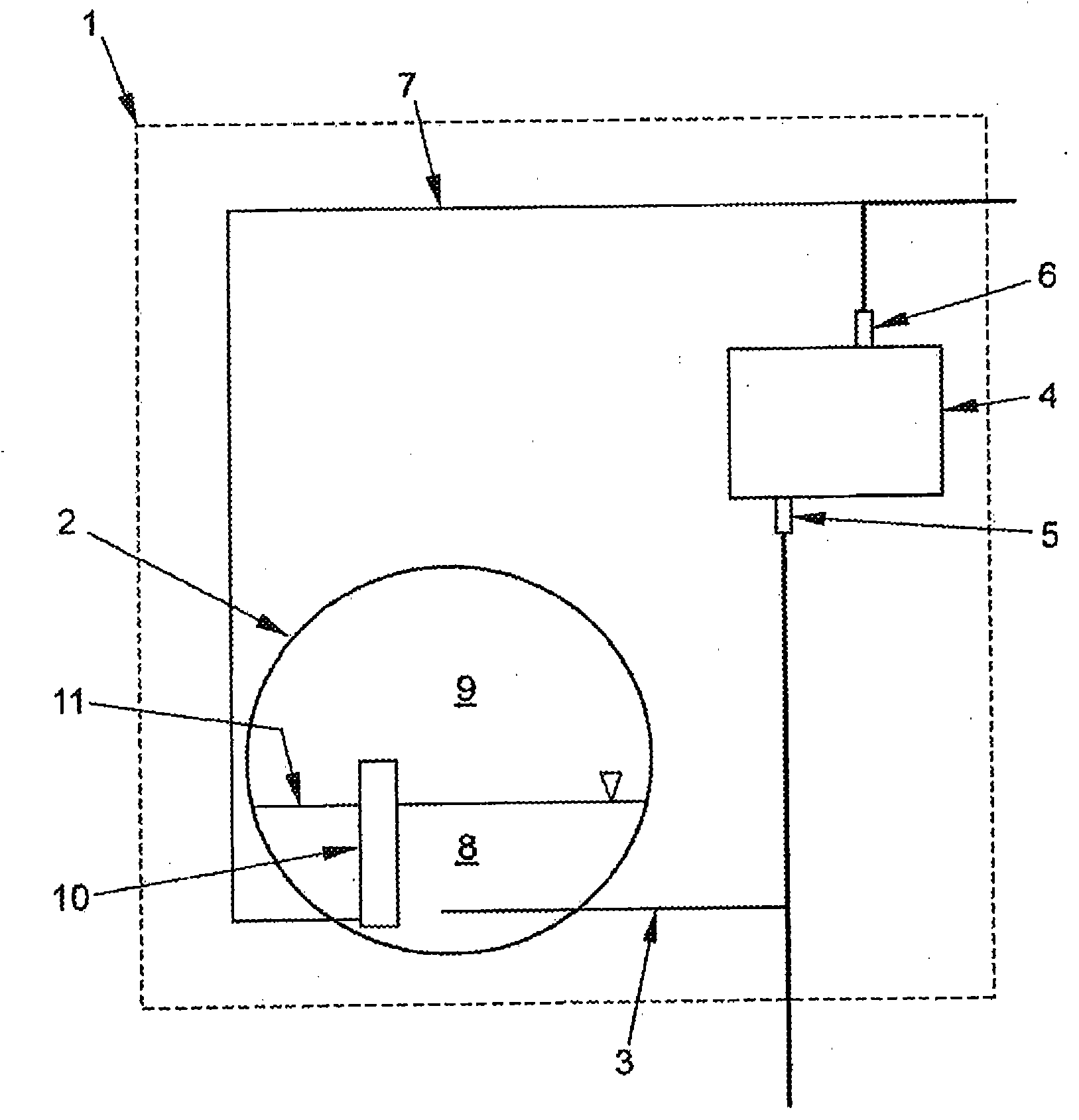
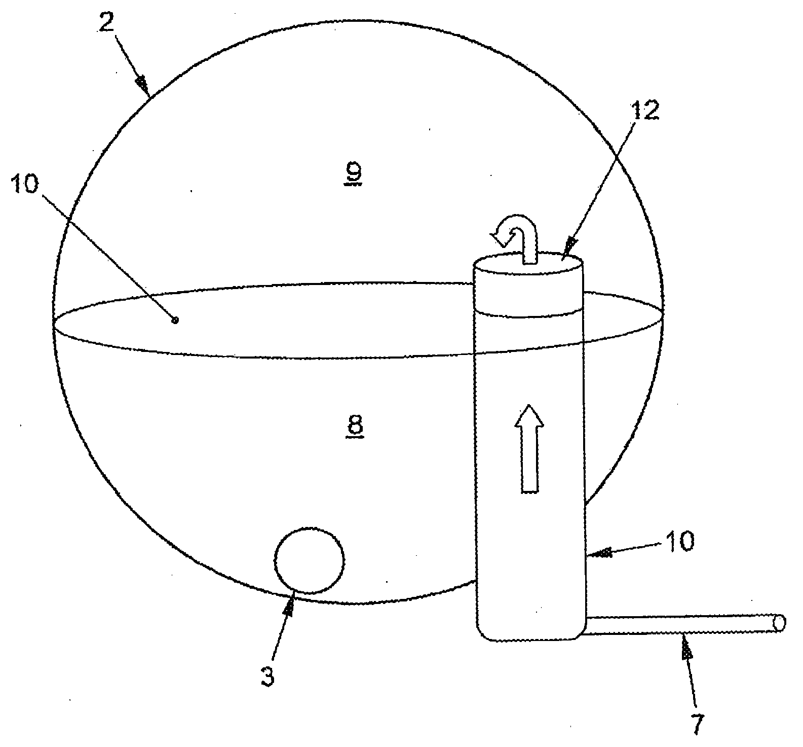
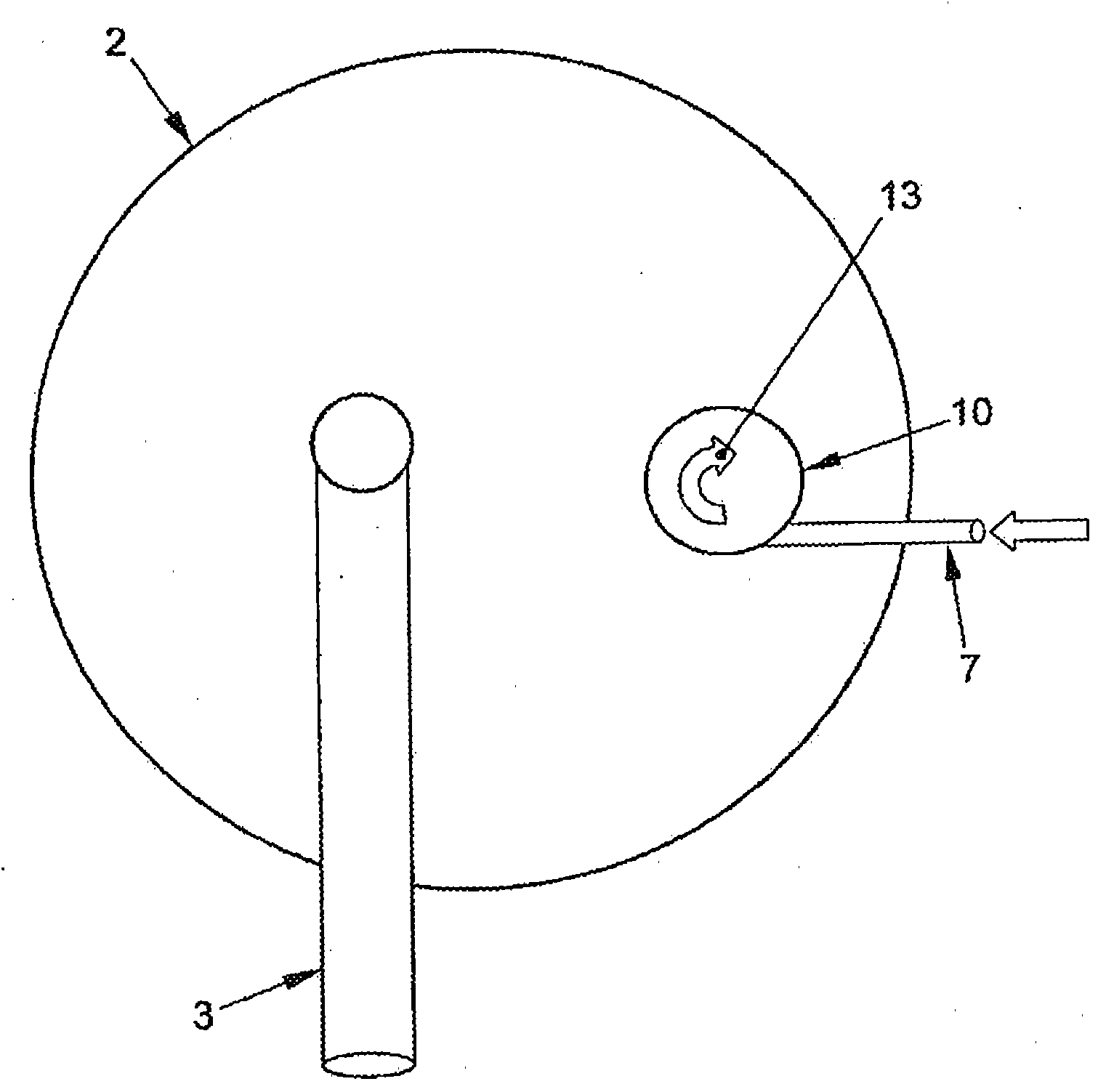
[0028] The following is based on Figures 1 to 3 The coolant circuit 1 according to the invention of the internal combustion engine (not shown) and the compensating container 2 included in the coolant circuit 1 will now be explained in more detail. The balancing container 2 is connected via a supply line 3 for the coolant to a heat exchanger 4 of the charge air cooler. The coolant passes through the supply line 3 through the inlet opening 5 into the heat exchanger 4 . In the upper region of the heat exchanger 4 there is a discharge hole 6 for the coolant with a branch, through which on the one hand the main volume flow is conveyed into the low-temperature region (not shown) and on the other hand through which the secondary volume flow is passed. It is led back into the equalization container 2 via the ventilation line 7 . The special properties of the ventilation line 7 here are the higher flow velocities occurring therein due to the smaller cross-sectional area in the venti...


PUM


Abstract

The invention relates to a coolant circuit (1) of an internal combustion engine, having a compensating vessel (2) and having a heat exchanger (4). The coolant passes into the exchanger (4) through a feed line (3). In an upper region of the heat exchanger (4) there is situated an outlet opening (6) for the coolant, having a branch through which, at one side, a main volume flow is supplied to a low-temperature region and through which, at the other side, a secondary volume flow is recirculated through a ventilation line (7) into the compensating vessel (2). Owing to the high flow speeds in the ventilation line (7), the air present in the heat exchanger (4) is supplied to the compensating vessel (2), which is positioned at a lower level. The ventilation line (7) is continued in the interior of the compensating vessel (2) as a vertical, hollow cylindrical tube portion (10) which therefore runs at least in sections below a water level (11) of the compensating volume (8) of the coolant in the compensating vessel (2). According to the invention, an arrangement of the compensating vessel (2) is attained in which the fill level (11) in the compensating vessel (2) is situated below the heat exchanger (4) during operation. By virtue of the ventilation line (7) being situated in sections below the fill level (11), pressure equalization between the heat exchanger (4) and the compensating vessel (2) is prevented. The negative pressure generated as a result of the extraction of the air present in the heat exchanger (4) is thus maintained, such that, despite the gradient existing within the coolant circuit (1), the coolant volume present in the heat exchanger (4) does not flow into those regions of the coolant circuit (1) which are situated at a lower level.

Description

technical field [0001] The invention relates to a coolant circuit of an internal combustion engine having a balancing container connected by means of a supply line to a heat exchanger of the coolant circuit associated with the internal combustion engine or a device of the internal combustion engine to be cooled, wherein the coolant The circuit also includes a ventilation line, via its heat exchanger, which is connected to the equalization container and which opens into the equalization container via an outlet opening, and wherein the ventilation line of the equalization container is arranged at least in sections in the balance during operation. Below the minimum fill level height (Fuellstandshoehe) set in the container. Furthermore, the invention relates to a compensating vessel for a coolant circuit of an internal combustion engine. Background technique [0002] Such a coolant circuit as well as a compensating vessel specified therefor are known, for example, from DE 29 44...

Claims


Application Information

Patent Timeline
IPC IPC(8): F01P11/02
CPCF01P11/028F01P11/029
Inventor M·托梅基N·施雷克
Owner VOLKSWAGEN AG
Why Eureka
Try Eureka