
Motor winding stripping method

A motor and winding technology, which is applied in the field of insulating film peeling, can solve the problems of deterioration of motor defect rate and deterioration of welding quality.

Active Publication Date: 2017-02-08
PANASONIC CORP
View PDF12 Cites 0 Cited by
  • Summary
  • Abstract
  • Description
  • Claims
  • Application Information

AI Technical Summary

Problems solved by technology

[0005] However, although the removal of the aluminum oxide layer as described in the patent literature is an important issue, no countermeasures have been taken for the disconnection and insulation coating residue in the previous process, that is, when the insulation coating of the electric wire is peeled off. Therefore, motor production Deterioration of defect rate and deterioration of welding quality have become problems
In particular, becomes a greater problem with thinner wires

Method used


Image

  • Motor winding stripping method
  • Motor winding stripping method
  • Motor winding stripping method

Examples


Embodiment approach

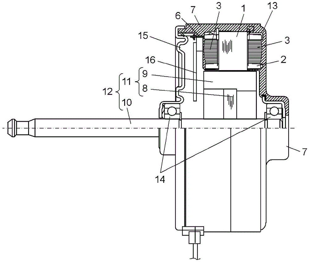
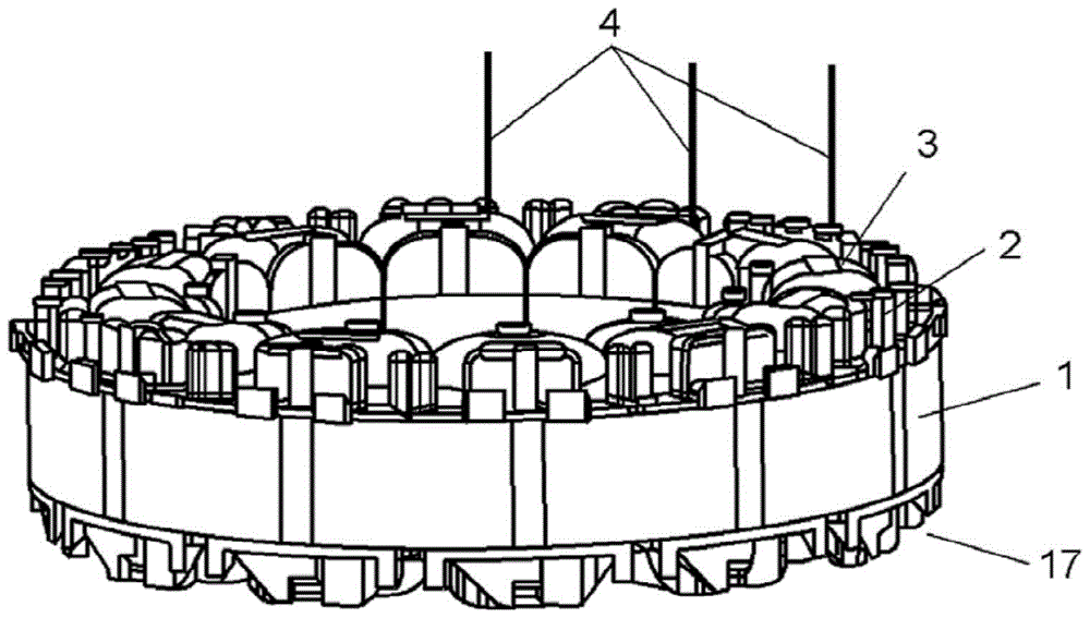
[0018] Hereinafter, embodiments of the present invention will be described using the drawings. figure 1 It is a configuration diagram showing a partial cross-section of the electric motor according to the embodiment of the present invention. figure 2 It is a figure which shows the concrete structural example of the winding completed product (finished stator) 17 of this electric motor. In this embodiment, an example of an electric motor, that is, a brushless motor that is installed in an air conditioner as an electric device and used to drive a blower fan will be described. In addition, in the present embodiment, an example of welding connection between the wire conductor and the terminal will be described. and, figure 2 The illustrated winding finished product 17 is constructed by using the winding stripping method of the motor winding of the present invention to peel off the insulating coating covering the tip of the wire. In addition, figure 1 The motor shown has such a wind...

Embodiment 1

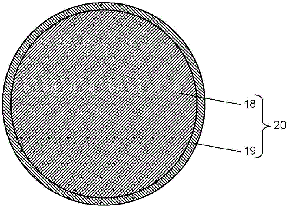
[0029] In the description of the embodiment, the following electric wire 20 is used: the conductor material is aluminum, the conductor diameter is 0.3 mm, the material of the insulation coating 19 is PEWN, and the insulation coating thickness is 0.012 mm. In addition, in the tension application direction acting on the winding end 4, a tension of 30 MPa was applied to the conductor of the electric wire and the cutting tool 101 was rotated at a rotation speed of 1500 r / min, thereby peeling off the insulating coating 19. At this time, the cutting tool movement direction 105 is the same as the tension application direction. In addition, the stopper for preventing the entry of the cutting tool 101 was adjusted to simultaneously peel off the portion of the conductor 18 with a depth of 0.002 mm. Under such conditions, the production of 1,000 motors was performed, and the defective rate of disconnection when the insulating coating was peeled off, the defective rate of residual insulati...


PUM

PropertyMeasurementUnit
diameteraaaaaaaaaa
thicknessaaaaaaaaaa
thicknessaaaaaaaaaa

Abstract

This method for separating windings of an electric motor is a method for separating an insulating film on an end part of a winding that is wound on a magnetic pole of a stator. This winding-separation method is characterized in that a winding end part is pulled into a tensioned state, and an insulating-film-separating device having a rotating cutting blade is moved, separating the insulating film. It is thereby possible to separate the insulating film without breaking the wire. Even if aluminum, which is weaker than copper wire or iron wire, is employed in a conductor of a winding, it will be possible to prevent breakage when the insulating film is being separated.

Description

Technical field [0001] The present invention relates to a technique of peeling the insulating film covering the tip of an electric wire with an insulating film covered by at least one layer of insulating film to expose a core wire and joining the core wire with other components by welding. In particular, it relates to a method of peeling a winding wire wound around a stator of a motor. Background technique [0002] In the past, copper wires were mainly selected as conductors of electric wires used in motors (motors). However, in recent years, the price of copper wires has risen, and improvements in the weight of the motor itself have been promoted, and the use of wires using conductors other than copper has gradually increased. [0003] Wires other than such copper wires, such as aluminum wires, have a strong aluminum oxide layer on their surface. Therefore, unless the insulating coating and the aluminum oxide layer are removed, soldering connections with terminals and wires are v...

Claims


Application Information

Patent Timeline
Patent Type & Authority Patents(China)
IPC IPC(8): H02K15/00H01F41/066
CPCH01F41/066H02K15/0068
Inventor 渡边彰彦高野笃史长谷川武彦畑矢英儿刘裕午近藤宪司
Owner PANASONIC CORP
Learn More