Thermal tandem rolling machine control device and thermal tandem rolling machine control method

A rolling mill control and tandem technology, applied in the direction of roll speed control, etc., can solve problems such as indefinite response, and achieve the effect of suppressing the disorder of speed balance

Active Publication Date: 2014-10-01
HITACHI LTD
View PDF7 Cites 1 Cited by
  • Summary
  • Abstract
  • Description
  • Claims
  • Application Information

AI Technical Summary

Problems solved by technology

In the method described in Patent Document 2, there is no description about taking this point ...

Method used


Image

  • Thermal tandem rolling machine control device and thermal tandem rolling machine control method
  • Thermal tandem rolling machine control device and thermal tandem rolling machine control method
  • Thermal tandem rolling machine control device and thermal tandem rolling machine control method

Examples


no. 2 Embodiment approach

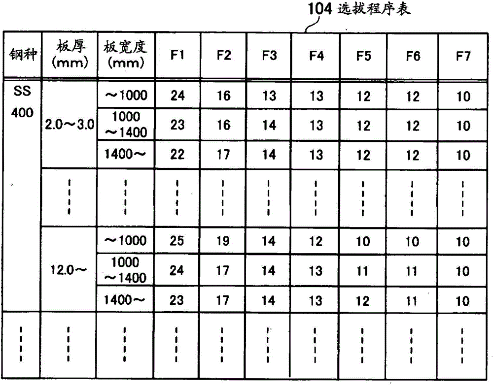
[0201] As the second embodiment of the present invention, an example is shown in which, when the upper limit speed exceeds the stand, the speed command correction unit 109 reduces the value of the reference rolling speed without reducing the value of the roll speed of the final stand. .

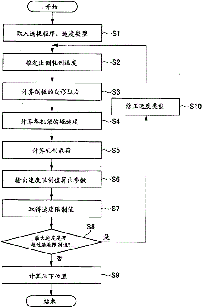
[0202] Figure 10 It is a flowchart showing the processing executed by the speed command correction unit 109 according to the second embodiment of the present invention.

[0203] First, the speed command correcting unit 109 determines whether or not the rolling of the steel plate 161 has been completed (step S41 ). When rolling ends, the process of the speed command correction part 109 ends, and if rolling is not ended, it transfers to step S42.

[0204] Next, in step S41, when the rolling is not completed, the speed command correction unit 109 determines whether there is a notification that the upper limit speed exceeds the stand from the upper limit speed determination unit 108 (step S42)...

no. 3 Embodiment approach

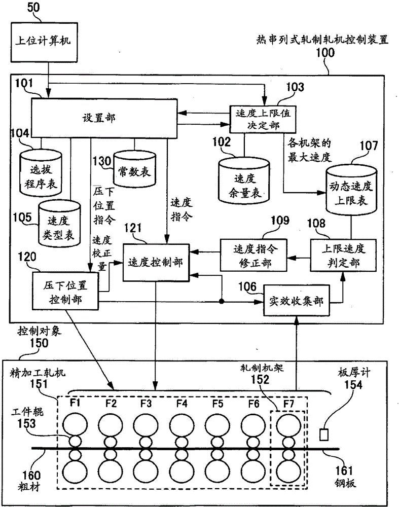
[0210] Figure 11 It is a block diagram showing a configuration example of a thermal tandem rolling mill control device according to a third embodiment of the present invention.

[0211] Hereinafter, as a third embodiment of the present invention, it is shown that the above-mentioned first embodiment is applied to a roughing mill 1102 provided with an edger 1110 and two rolling stands R1, R2, and a roughing mill 1102 provided with five rolling stands 152 ( An example of the case where the control object 1101 constituted by the finishing rolling mill 1103 of F1 to F5). Such a configuration of the control object 1101 is called a so-called small rolling mill.

[0212] In this embodiment, it is necessary to consider the upper limit value of the roll speed of the edger 1110 and the maximum value of the rolling speed in addition to the seven rolling stands in total. When the steel plate 1105 is thick, or when the thickness difference between the slab 1104 and the steel plate 1105 ...


PUM


Abstract

The invention provides a thermal tandem rolling machine control device which maximally exert equipment capability and suppress speed balance disorder between rolling frames in rolling, and a thermal tandem rolling machine control method. A thermal tandem rolling machine (151) is used as a control object, a structure which is described is adopted in the thermal tandem rolling machine control device (100) in which workpiece rollers (153) that are equipped in a plurality of rolling frames (152) continuously control rolling of a steel plate. The thermal tandem rolling machine control device aims at different risks of reaching an upper limit of a rolling speed according to steel plate characteristic and can set a speed allowance for each steel plate, thereby appropriating a maximal value of the rolling speed which can be set by setting operation. Hereon, preferably, when the rolling speed of a specific rolling frame (152) in rolling reaches the upper limit of the rolling speed, controlling is performed for reducing the rolling speed of each rolling frame (152), thereby minimizing speed balance disorder among the rolling frames (152).

Description

technical field [0001] The invention relates to a hot tandem rolling mill control device and a hot tandem rolling mill control method. Background technique [0002] In the hot tandem rolling mill, except that the rotational speed (hereinafter, simply referred to as "speed"), torque, and motor power of the work rolls of each rolling stand do not become too large, the Balance between control racks is also important. In particular, if the speed balance between the rolling stands is poor, the steel plate is sometimes loosened and sometimes tensed between the rolling stands, so that unstable rolling occurs and the quality of the steel plate deteriorates. In order to increase the throughput, it is necessary to increase the rolling speed to a high value, but if the speed and torque of a specific rolling stand are limited by the upper limit of the equipment during rolling, the speed balance among the rolling stands will collapse. , causing the above-mentioned problem. [0003] In...

Claims


Application Information

Patent Timeline
IPC IPC(8): B21B37/46
Inventor 鹿山昌宏林刚资小林拓也
Owner HITACHI LTD
Why Eureka
Try Eureka