
Direct-drive type numerical control hobbing cutter frame

A gear hobbing cutter, direct-drive technology, applied in the direction of gear teeth, gear cutting machines, components with teeth, etc., can solve the problems of transmission stability limitation, high heat generation of gear transmission, and difficulty in gear processing. Compact structure, enhanced tool shifting torque, enhanced tool shifting resolution effect

Active Publication Date: 2014-10-01
ZHEJIANG RICHUANG MECHANICAL & ELECTRICAL TECH
View PDF6 Cites 6 Cited by
  • Summary
  • Abstract
  • Description
  • Claims
  • Application Information

AI Technical Summary

Problems solved by technology

Ordinary CNC gear hobbing tool post adopts mechanical transmission, and the structure is complex. For example, when gear pair transmission is generally used, the precision of the main shaft of the tool post is easily affected by the manufacturing accuracy of the gear pair, the gap between the gear pair, etc., and the stability of the transmission is limited.
Moreover, the precision of the transmission gear requires level 5 (new standard) precision, the gear processing is difficult, and the teeth must be ground during processing, the efficiency is low, and the processing cost is high
Especially when doing high-speed machining, the gear transmission generates a lot of heat, and the temperature is not easy to control

Method used


Image

  • Direct-drive type numerical control hobbing cutter frame
  • Direct-drive type numerical control hobbing cutter frame
  • Direct-drive type numerical control hobbing cutter frame

Examples


Embodiment

[0028]Embodiment: The embodiment of the present invention is illustrated by specific specific examples below. Those skilled in the art can easily understand other advantages and effects of the present invention from the contents disclosed in this specification. Descriptions such as "below", "top", "bottom", "front" are defined in the usual sense, e.g., with reference to the definition of the direction of gravity, the direction of gravity is below, and the opposite direction is above, similarly in The top is the top or the top, the bottom is the bottom or the bottom, and the left side of the direction of the drawing is the front end. These orientation descriptions are only for the convenience of description, and are not used to limit the scope of the present invention. The change of its relative relationship Or adjustment, without substantive changes in technical content, should also be regarded as the scope of the present invention can be implemented.

[0029] Such as figure ...


PUM


Abstract

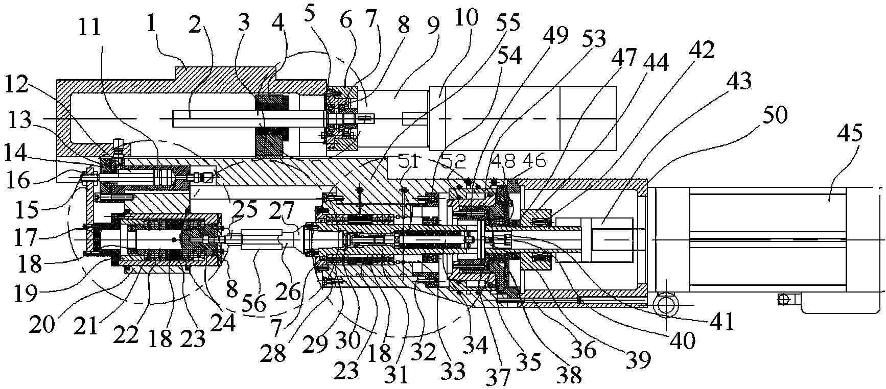
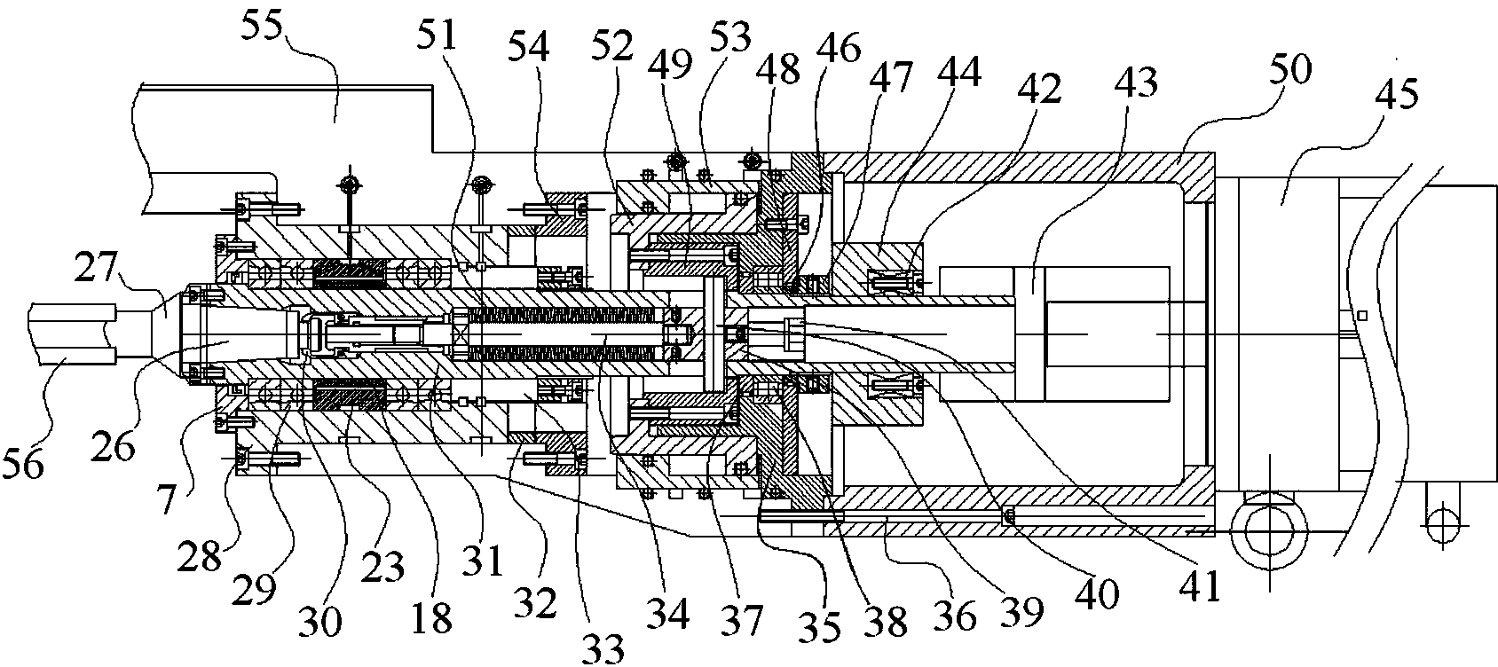
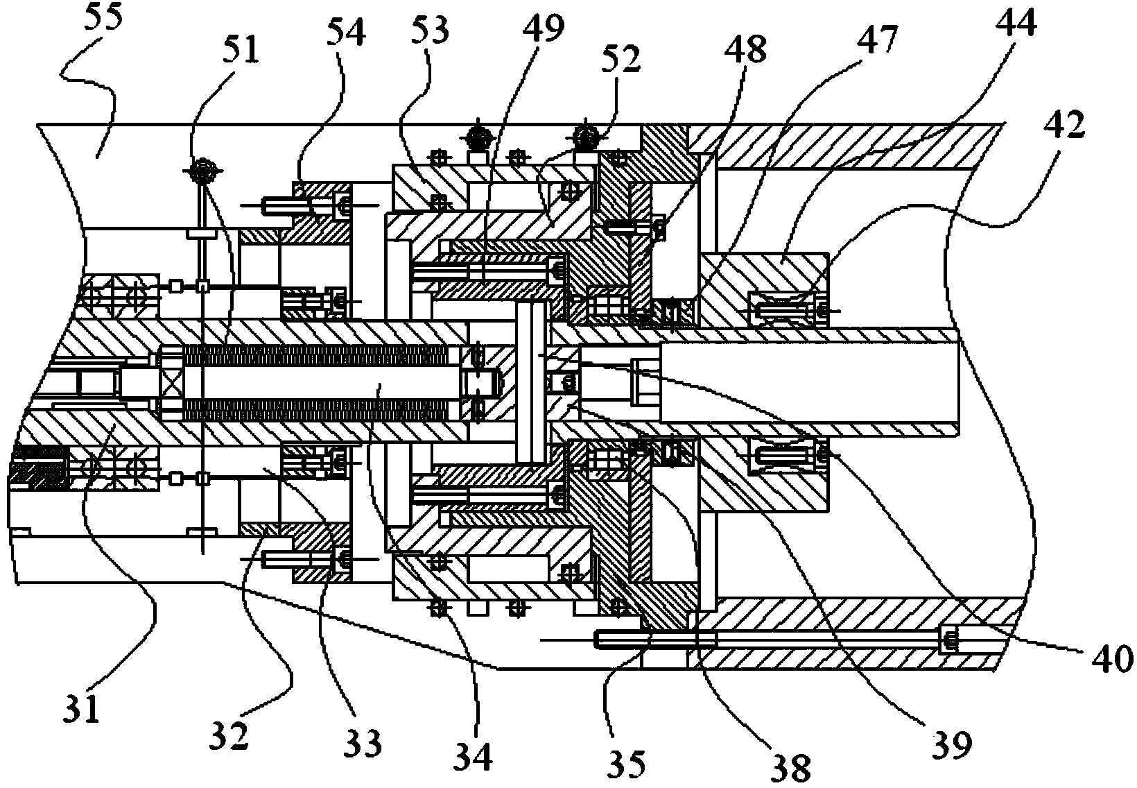
The invention discloses a direct-drive type numerical control hobbing cutter frame. The direct-drive type numerical control hobbing cutter frame comprises a cutter frame body, a cutter frame sliding plate, a cutter frame main shaft assembly, a cutter rod assembly, a cutter frame auxiliary supporting assembly and a channeling cutter assembly; the cutter frame body comprises a cutter frame main body; the cutter frame sliding plate comprises a sliding plate body; the sliding plate body and the channeling cutter assembly are arranged on the cutter frame main body; the left side of the upper half portion of the sliding plate body is provided with a semicircular support and the right side of the upper half portion of the sliding plate body is provided with a cutter frame main shaft installing hole; the cutter frame auxiliary supporting assembly is arranged on the semicircular support; the cutter frame main shaft assembly is partially arranged in the cutter frame main shaft installing hole; one end of the cutter rod assembly is connected with the cutter frame main shaft assembly and the other end of the cutter rod assembly is connected with the cutter frame auxiliary supporting assembly; the cutter frame auxiliary supporting assembly is arranged on the semicircular support of the sliding plate and is opposite to the cutter frame main shaft assembly. The direct-drive type numerical control hobbing cutter frame is short in cutter replacement time, stable and reliable in cutter replacement action, high in rotating and machining accuracy and simple and compact in structure.

Description

Technical field: [0001] The invention relates to the technical field of mechanical manufacturing, and more specifically relates to a numerically controlled gear hobbing tool holder. Background technique: [0002] CNC gear hobbing tool holder is one of the main components of CNC gear hobbing machine tools. The direct-drive CNC hobbing tool holder mainly has the advantages of short transmission chain, high transmission precision, compact structure, and easy temperature control. Ordinary CNC gear hobbing tool post adopts mechanical transmission, and its structure is complicated. For example, when gear pair transmission is generally used, the precision of the main shaft of the tool post is easily affected by the manufacturing accuracy of the gear pair, the gap between the gear pair, etc., and the stability of the transmission is limited. Moreover, the precision of the transmission gear requires Class 5 (new standard) precision, and the machining of the gear is difficult, and th...

Claims


Application Information

Patent Timeline
IPC IPC(8): B23F23/12
Inventor 徐长春陶新根闵中华周伟强
Owner ZHEJIANG RICHUANG MECHANICAL & ELECTRICAL TECH
Learn More