Manufacturing method of cast-in-place concrete ribbed floor

A production method and technology for a multi-rib floor, which can be applied to floors, building components, buildings, etc., can solve the problems of small application range of the multi-rib floor, and achieve the advantages of low cost, reduced building height, and simple production process. Effect

Inactive Publication Date: 2017-03-01
郎佃富
View PDF4 Cites 0 Cited by
  • Summary
  • Abstract
  • Description
  • Claims
  • Application Information

AI Technical Summary

Problems solved by technology

[0002] At present, the commonly used lightweight cast-in-place floors in building construction mainly include dense ribbed floors and hollow-core floors. The thickness of the roof itself is relatively small, and it occupies relatively little building floor height. However, since the bottom surface of the densely ribbed floor is rib beams arranged vertically and horizontally, it is necessary to add a In this way, the ribbed floor loses its advantage in occupying the building's floor height. In addition, cumbersome steps such as demoulding are required during the construction process. Therefore, the application range of the densely ribbed floor is getting smaller and smaller, and it is gradually being used. hollow floor replaced by

Method used


Image

  • Manufacturing method of cast-in-place concrete ribbed floor
  • Manufacturing method of cast-in-place concrete ribbed floor
  • Manufacturing method of cast-in-place concrete ribbed floor

Examples


Embodiment

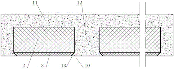
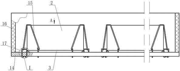
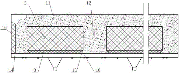
[0052] The manufacturing method of the cast-in-place concrete multi-ribbed floor cover of the present invention includes the following steps:

[0053] ①Support bottom formwork 14 and side formwork 16;

[0054] ②Place the bottom plate 3 of the filler on the bottom template 14, leave a gap between the adjacent bottom plates 3 for pouring the ribs 12, and each side bottom of the bottom plate 3 is provided with a concave mold 10;

[0055] ③Install two horse nails 17 on the top surface of the bottom template 14 on each side of the bottom plate 3. The end of each horse nail 17 is closely attached to the side wall of the bottom plate 3 to prevent the bottom plate 3 from moving horizontally. The distance from the top surface of the bottom template 14 is 20mm, and the horse nail 17 is fixed on the bottom template 14 by the following method:

[0056] a. Place a cushion block 18 on the bottom template 14. The length of the cushion block 18 is parallel to the edge of the bottom surface of the bot...


PUM


Abstract

The invention discloses a cast-in-place concrete dense rib floor system and a manufacturing method thereof. The cast-in-place concrete dense rib floor system comprises a floor plate, wherein multiple rib beams which are arranged in a criss-cross mode are arranged on the bottom face of the floor plate, filling bodies are arranged between adjacent rib beams. The filling bodies comprise upper bodies and bottom plates, the bottom plates are made of hard materials, the upper bodies are mounted at the top faces of the bottom plates, the bottom faces of the bottom plates are flushed with the bottom faces of the rib beams, dies are arranged at the bottoms of the lateral sides of the bottom plates, supporting claws which are the same with the dies in shape are arranged in the dies, and the supporting claws are connected with the side walls of the rib beams. The cast-in-place concrete dense rib floor system has the advantages that a suspended ceiling isn't needed, and demolding isn't needed. Compared with the prior art, the cast-in-place concrete dense rib floor system can effectively reduce the thickness of the cast-in-place concrete dense rib floor system, reduces the occupied floor height of buildings, and simplifies manufacturing technology. Dense rib floor system products are competitive in market, and the filling bodies are simple in manufacturing technology, low in cost, and not easy to damage during transportation.

Description

Technical field [0001] The invention relates to a multi-ribbed floor for construction, in particular to a method for manufacturing a cast-in-place concrete multi-ribbed floor. Background technique [0002] At present, the commonly used light cast-in-place slabs in building construction mainly include ribbed slabs and hollow slabs. The hollow slab has a relatively large thickness and occupies a relatively large number of floors. The thickness of the cover itself is relatively small, and the floor height of the building is relatively small. However, because the bottom surface of the multi-ribbed slab is a rib beam arranged vertically and horizontally, it is necessary to add an additional at the bottom of the multi-ribbed slab when the overall appearance of the room is required. As a result, the multi-ribbed slab loses its advantage in occupying the height of the building. In addition, the construction process requires cumbersome steps such as demoulding. Therefore, the application ...

Claims


Application Information

Patent Timeline
Patent Type & Authority Patents(China)
IPC IPC(8): E04B5/36E04G21/00
Inventor 郎佃富王敦强
Owner 郎佃富
Why Eureka
Try Eureka