
Drum-shaped stabilizer for drilling machine

A stabilizer, drum-shaped technology, applied in drill pipes, drill pipes, drilling equipment and other directions, can solve the problems of short service life of drill pipe stabilizers, shortened service life of enhanced sleeves, and increased operating costs of drilling rigs, etc., to achieve a stable effect. Good, increase the service life, the effect of simple structure

Active Publication Date: 2014-10-01
ZHEJIANG ZHONGRUI ENG MACHINERY
View PDF5 Cites 0 Cited by
  • Summary
  • Abstract
  • Description
  • Claims
  • Application Information

AI Technical Summary

Problems solved by technology

[0002] The stabilizers of general large-scale drilling rigs use drill pipe stabilizers. The middle part of the rotating cylinder of the drill pipe stabilizer is installed with drill pipe vertically. There are six righting arms, and a wooden wear-resistant block is installed at the end where the righting arm meets the outer wall of the rotating cylinder. The rotation of the drill pipe drives the rotating cylinder, and the rotating cylinder and the wooden wear-resistant block rub against each other. The rod stabilizer keeps the drill rod in place through the contact between the centralizing arm and the inner wall of the hole, but this kind of drill rod stabilizer has a short service life and is easy to wear. After wear, the entire drill rod will be bent, resulting in damage to the entire drill tool flow
[0003] Patent No. 2007800291842 describes a drill string stabilizer. This stabilizer is fitted with a reinforcement sleeve on the drill pipe and as close to the drill bit as possible, and the outer diameter of the reinforcement sleeve is approximately the same as the diameter of the drill bit. , the reinforced sleeve can reduce the sway of the drill bit in the drilling hole and reduce the sway of the drill bit from the straight drilling direction, but this mechanism cannot guarantee that the drill rod will not be bent due to the torque it bears during the work, and at the same time Because the reinforced sleeve needs to be in contact with the discharged material when the drilling rig is working, the service life of the reinforced sleeve is reduced, which will greatly increase the working cost of the drilling rig

Method used


Image

  • Drum-shaped stabilizer for drilling machine
  • Drum-shaped stabilizer for drilling machine
  • Drum-shaped stabilizer for drilling machine

Examples


Embodiment 1

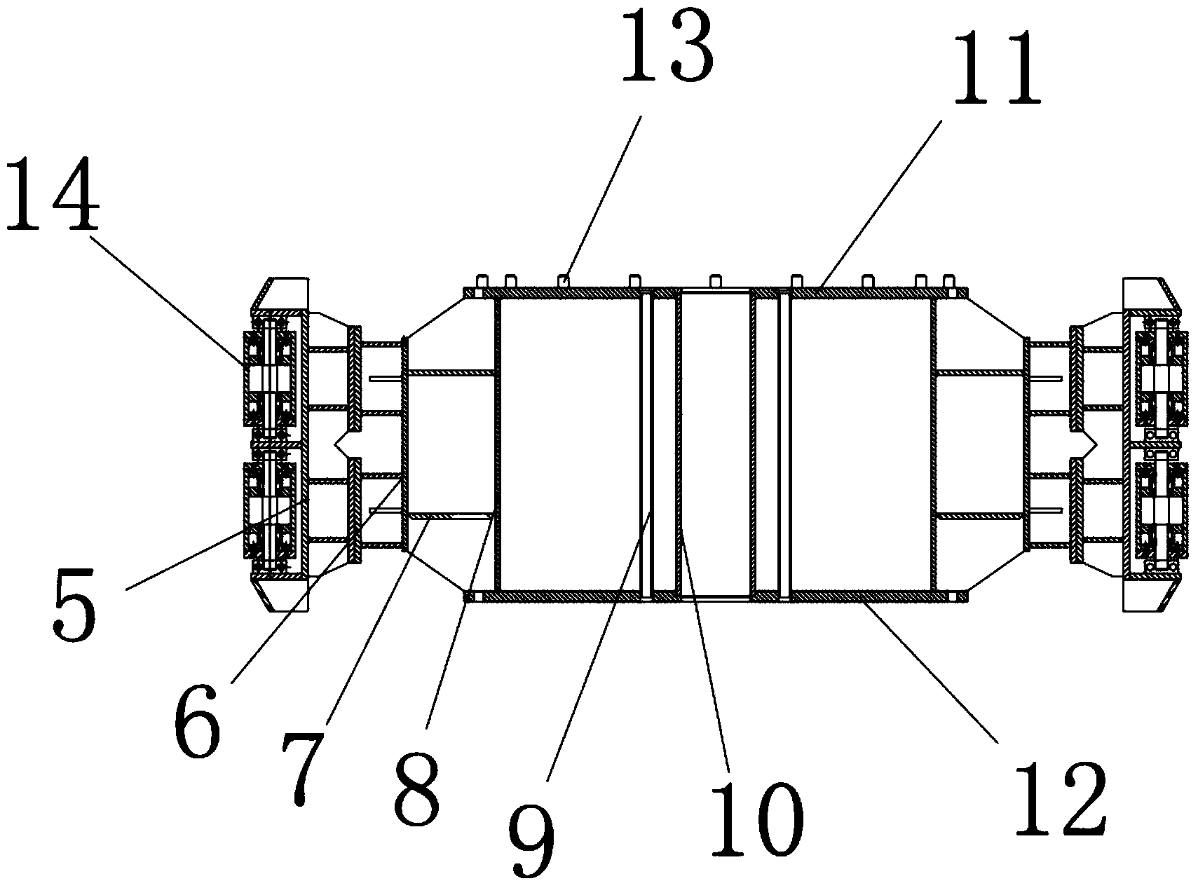
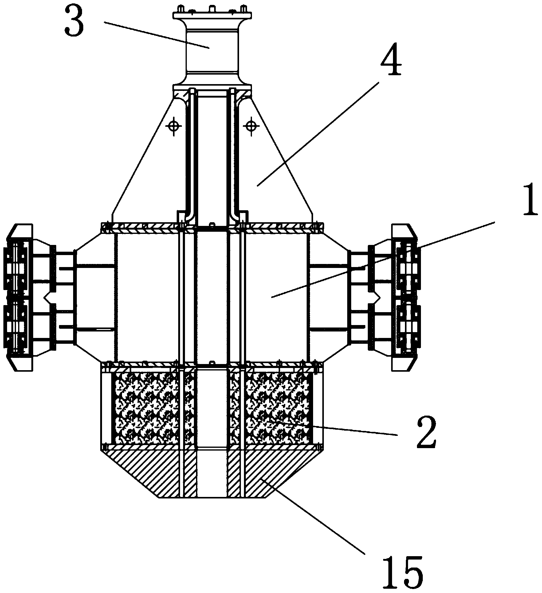
[0038] Install the variable-diameter short-connection 4 on the drum-shaped stabilizer 1, install the drill pipe 3 on the variable-diameter short-connection 4, and after filling the counterweight sand 24 in the counterweight 2, install the counterweight 2 on the drum-shaped stabilizer. On the lower end surface of the device 1, then a drill bit 15 is installed on the lower end surface of the counterweight 2, and then the drill rod 3 is connected to the lower end surface of the rotating device of the drilling rig, and the entire drill bit 15 is installed on the drilling rig together with the drum stabilizer 1, and then Turn on the drilling rig and start to work. During work, the construction department is filled with water to facilitate the drilling rig. The drill bit 15 is rotated to drill holes. The drill bit 15 is arranged with an air inlet pipe and a slurry discharge pipe, and the gas is passed through the drilling rig along the upper and lower edges. The air pipe 9 transports...

Embodiment 2

[0040] When the size of the drill bit of the drilling rig becomes smaller and cannot match the counterweight 2, it is necessary to change an assembly method, such as Figure 11 As shown, install the variable diameter short connection 4 on the drum stabilizer 1, install the drill pipe 3 on the variable diameter short connection 4, after the counterweight sand 24 is filled in the counterweight 2, the counterweight 2 is installed on the On the lower end surface of the drum-shaped stabilizer 1, an adapter 16 is installed on the lower end surface of the counterweight 2, and a drill bit 15 is installed on the lower end surface of the adapter 16, and then the drill rod 3 is connected to the lower end surface of the rotating device of the drilling rig , install the whole drill bit 15 together with the drum-shaped stabilizer 1 on the drilling rig, then turn on the drilling rig and start working, the rotating device drives the drill pipe 3 to rotate, and the rotation of the drill pipe 3 ...

Embodiment 3

[0042] When the mounting hole of the drum stabilizer installed on the drilling rig is too large, an elastic telescopic connection or a cylinder connection can be installed between the outer cylinder 6 of the drum stabilizer and the roller bracket 5, so that the entire drum stabilizer The roller 14 leans against the inner wall of the mounting hole so that the drum stabilizer can work normally.


PUM


Abstract

The invention relates to a drum-shaped stabilizer for a drilling machine. The drum-shaped stabilizer comprises air inlet pipes, an inner tube and a slurry discharge pipe, wherein the slurry discharge pipe is vertically arranged in the center part of the inner tube; two sides of the slurry discharge pipe are vertically and symmetrically provided with a plurality of air inlet pipes; the upper end surface and the lower end surface of the inner tube are respectively provided with a flange and a lower bottom plate which are communicated with the slurry discharge pipe and the air inlet pipes; a circle of connecting holes are uniformly distributed in the outer ring parts of the upper end surface of the flange and the lower end surface of the lower bottom plate; an outer ring of the inner tube is connected with the outer tube through a round rib plate; a plurality of roller support frames are uniformly and symmetrically arranged on an outer ring of the outer tube; and a plurality of rollers are vertically arranged on the roller support frames side by side. The drum-shaped stabilizer has the characteristics that the structure is simple; the abrasion cannot easily occur; the stabilizing effect is good; the service life is long; the production cost is low; and the replacement and the maintenance are convenient, and the like.

Description

technical field [0001] The invention relates to the field of manufacturing stabilizers for large drilling rigs, in particular to a drum stabilizer for drilling rigs. Background technique [0002] The stabilizers of general large-scale drilling rigs use drill pipe stabilizers. The middle part of the rotating cylinder of the drill pipe stabilizer is installed with drill pipe vertically. There are six righting arms, and a wooden wear-resistant block is installed at the end where the righting arm meets the outer wall of the rotating cylinder. The rotation of the drill pipe drives the rotating cylinder, and the rotating cylinder and the wooden wear-resistant block rub against each other. The rod stabilizer keeps the drill rod in place through the contact between the centralizing arm and the inner wall of the hole. However, this kind of drill rod stabilizer has a short service life and is easy to wear. After wear, the entire drill rod will be bent and the entire drill tool will be...

Claims


Application Information

Patent Timeline
IPC IPC(8): E21B17/10
Inventor 张良夫毛伟周跃阳
Owner ZHEJIANG ZHONGRUI ENG MACHINERY
Features
  • Generate Ideas
  • Intellectual Property
  • Life Sciences
  • Materials
  • Tech Scout
  • Unparalleled Data Quality
  • Higher Quality Content
  • 60% Fewer Hallucinations
Learn More