Filling pile spiral hoisting slurry drill pipe

A technology of spiral lifting and cast-in-place piles, which is applied in the direction of drill pipes, drill pipes, drilling equipment, etc., can solve the problems of thick slurry and mud blocks that are difficult to discharge from the hole of the pile, increased mud concentration, etc., and achieve the purpose of improving practical value Effect

Inactive Publication Date: 2014-10-01
SHANGHAI SHANSHUN CIVIL ENG TECH +1
View PDF7 Cites 21 Cited by
  • Summary
  • Abstract
  • Description
  • Claims
  • Application Information

AI Technical Summary

Problems solved by technology

However, this drill bit is limited to the process of mud reverse circulation (that is, sucking mud from the drill bit). If the construction method adopts mud circulation (that is, mud is sprayed out from the

Method used


Image

  • Filling pile spiral hoisting slurry drill pipe
  • Filling pile spiral hoisting slurry drill pipe

Examples


Embodiment Construction

[0015] The present invention will be described in more detail below with reference to the accompanying drawings. It should be noted that, these drawings are all in a very simplified form and use inaccurate ratios, and are only used to facilitate and clearly describe the embodiments of the present invention.

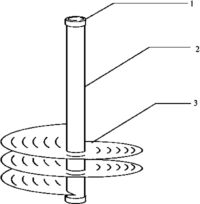
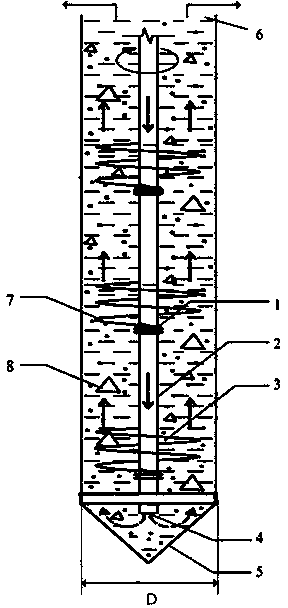
[0016] see figure 1 and figure 2 , the cast-in-place pile auger pipe provided by the present invention includes one or several sections of hollow drill pipe 2 and a drill pipe joint 1 connected with the hollow drill pipe 2. The outer surface of the hollow drill pipe 2 is provided with a helical blade 3, and each section of the hollow drill pipe is provided with a spiral blade 3. The rods 2 are connected through a drill pipe joint 1 , and a spray port 4 is provided at the connection between the first section of the hollow drill rod 2 and the drill bit 5 .

[0017] Wherein, the helical blade 3 is arranged on the lower section of the hollow drill rod 2, and the length of ...


PUM


Abstract

The invention discloses a filling pile spiral hoisting slurry drill pipe, which comprises a section or a plurality of sections of hollow drill pipes and drill pipe joints connected with the hollow drill pipes, wherein spiral blades are arranged on the outer surfaces of the hollow drill pipes; every two sections of hollow drill pipes are connected through the drill pipe joints; and a slurry spraying opening is formed in a connecting part of the first section of hollow drill pipe and a drill bit. Generally, The spiral blades are welded onto a hollow drill hole and are arranged at the lower section of the hollow drill pipes; and the length of the spiral blades is 1/4 to 1/2 of the total length of the hollow drill pipes, and the diameter of the spiral blades is smaller than the diameter of the drill bit. During the construction, the spiral blades rotate in the positive direction along the drill pipes; the upward hoisting force is generated on slurry at the lower section of a pile hole, and mud blocks in the slurry; and meanwhile, downward thrust is generated on the drill pipes. The drill pipe has the effects of connecting the drill bit and transmitting the drill bit and also has the effect of hoisting the slurry, so that the practical value of the drill pipe is improved.

Description

technical field [0001] The invention relates to a drill pipe, in particular to a screw-lifting mud drill pipe for cast-in-place piles. Background technique [0002] At present, during the construction of conventional bored piles, the functions of the drill pipe are as follows: one is to connect the drill bit with the construction equipment through the connection of multiple drill pipes when the drill bit sinks; The equipment is passed to the drill bit, which causes the bit to rotate. [0003] The patent number: "ZL 20132 0103907.1" and the Chinese patent with the patent name "A soft soil foundation cast-in-place pile forced cutting drill bit" provides a drill bit. The beneficial effects of using the drill bit are that the drill bit sinks quickly and the construction efficiency is high. However, the drill bit is only used for the mud reverse circulation process (that is, the mud is sucked from the drill bit). If the construction method adopts the mud positive circulation (th...

Claims


Application Information

Patent Timeline
IPC IPC(8): E21B17/22
Inventor 李庭辉周铮刘军周蓉峰
Owner SHANGHAI SHANSHUN CIVIL ENG TECH
Why Eureka
Try Eureka