
Built-in outer rotor motor direct drive lawn mower drive wheel and lawn mower

A technology of outer rotor motor and driving wheel, which is applied in the direction of lawn mowers, electric components, agricultural machinery and implements, etc., and can solve the problems of high speed of inner rotor motor, lower transmission accuracy and reliability, and influence

Active Publication Date: 2016-06-08
ZHEJIANG YAT ELECTRICAL APPLIANCE CO LTD
View PDF7 Cites 0 Cited by
  • Summary
  • Abstract
  • Description
  • Claims
  • Application Information

AI Technical Summary

Problems solved by technology

Existing lawn mowers generally have wheels and a drive motor that drives the wheels to rotate. The output end of the drive motor is connected to the rotating shaft of the wheels to drive the wheels to rotate. The lawn mower with this structure has the following defects: 1. The drive motor is located at the wheel Externally, there must be a part for installing the drive motor on the lawn mower, and the structure is relatively complicated; 2. The drive motor takes up a certain space and affects the setting of other mechanisms on the lawn mower, reducing the accuracy and reliability of the transmission; 3. Ordinary The inner rotor motor has high speed and relatively small moment of inertia

Method used


Image

  • Built-in outer rotor motor direct drive lawn mower drive wheel and lawn mower
  • Built-in outer rotor motor direct drive lawn mower drive wheel and lawn mower
  • Built-in outer rotor motor direct drive lawn mower drive wheel and lawn mower

Examples


Embodiment 1

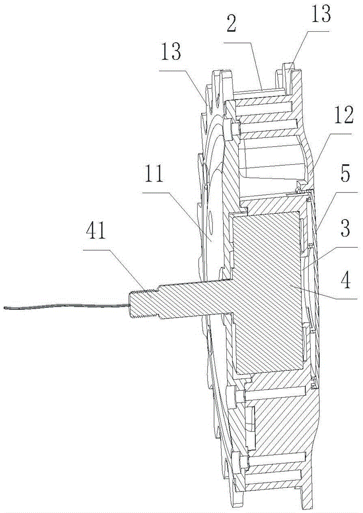
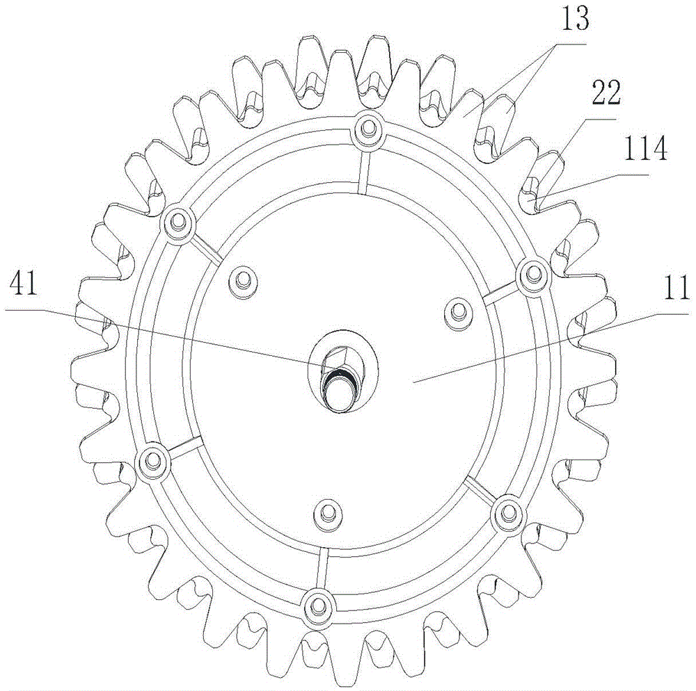
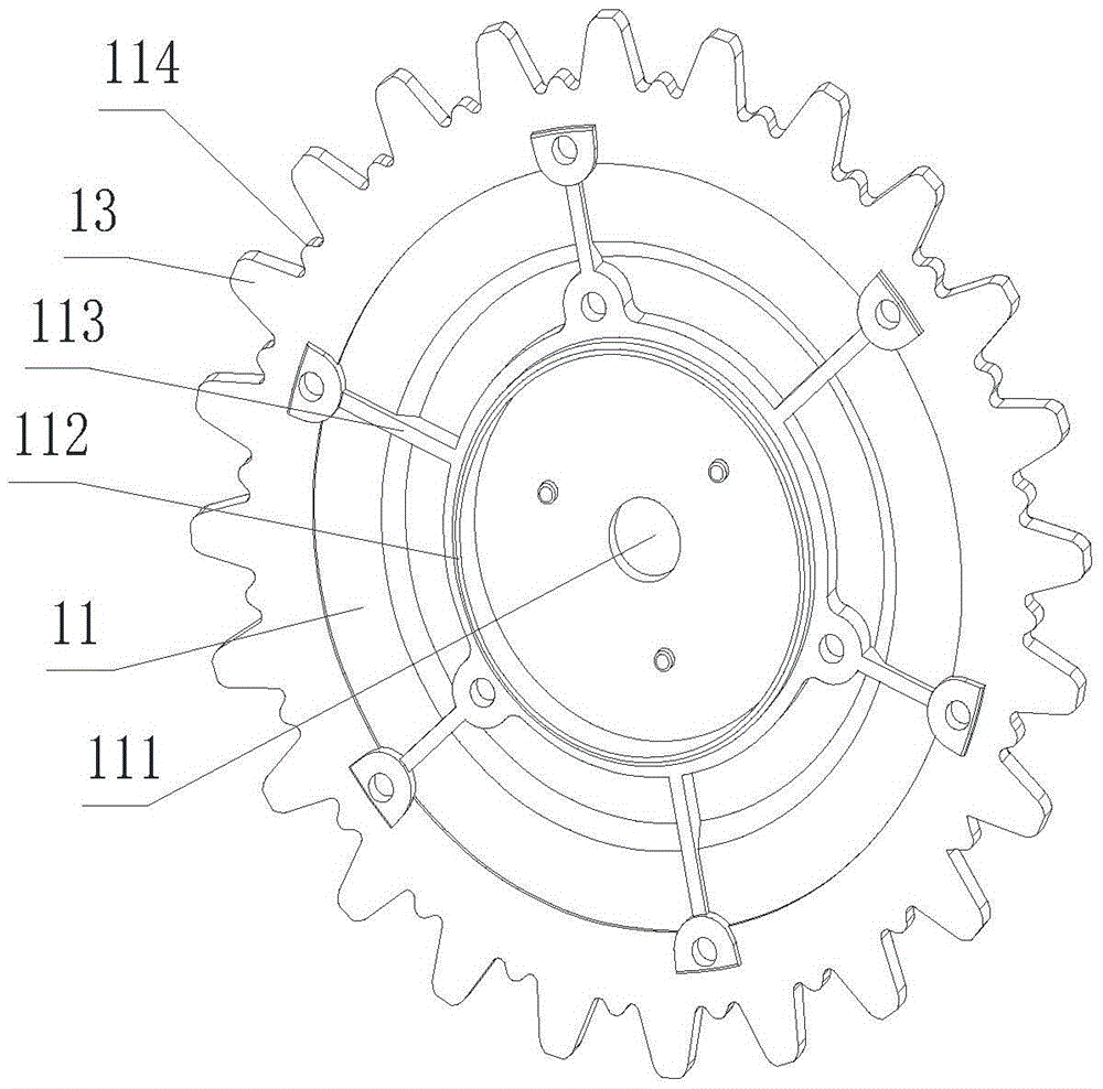
[0023] Such as Figures 1 to 5 As shown, the drive wheel of the built-in external rotor motor direct drive lawn mower is composed of the wheel side cover I11, the wheel side cover II12 and the wheel body 2 sandwiched between the wheel side cover I11 and the wheel side cover II12. The main body of the driving wheel, the wheel side cover II12 and the wheel body 2 are integrally formed. The wheel side cover I11, the wheel side cover II12 and the wheel body 2 form a cavity 3, and the outer rotor motor 4 is installed in the cavity 3. The outer rotor part of the outer rotor motor 4 is fixedly arranged relative to the main body of the driving wheel, and the stator part of the outer rotor motor 4 has a fixing part 41 protruding from the wheel side cover I11 to the outside of the driving wheel main body, and the fixing part 41 is a tubular or hollow cylinder Shaped structure, the hollow part is used to lead out the connecting wires of the outer rotor motor 4, and the wheel side cover I...

Embodiment 2

[0025] Such as Figure 6 As shown, the lawn mower includes a body 6, two universal wheels 8 are installed in front of the bottom of the body 6, and two driving wheels 9 are installed on both sides of the rear, wherein the driving wheels 9 are the embedded outer rotors in the first embodiment The motor directly drives the drive wheel of the lawn mower, wherein the fixing member 41 is fixedly connected to the body 6, and the body 6 has a control system electrically connected to the outer rotor motor; A cutterhead 72 is installed on the cutterhead 72, and a blade 73 is installed on the cutterhead 72. A plurality of guard columns 74 are arranged on the cutterhead frame 71. There is a distance between adjacent two guard columns 74. The cutterhead 72 and the blade 73 surround the guard column. In the middle of 74, the bottom surface of the body 6 is provided with some elongated ribs 61 around the cutter head frame 71. The extension direction of the ribs 61 is consistent with the dir...


PUM


Abstract

The present invention provides a direct-drive lawnmower drive wheel and a lawnmower with an embedded external rotor motor, including a wheel side cover I, a wheel side cover II and a wheel sandwiched between the wheel side cover I and the wheel side cover II. The main body of the driving wheel assembled by the wheel body, the wheel side cover I, the wheel side cover II and the wheel body form a cavity, the outer rotor motor is installed in the cavity, and the outer rotor part of the outer rotor motor Relative to the main body of the driving wheel, the inner stator part of the outer rotor motor has a fixed shaft extending out of the main body of the driving wheel through the wheel side cover I. Shaft hole I. The invention installs the outer rotor motor inside the drive wheel, and directly drives the drive wheel of the lawnmower through the outer rotor motor, which has good transmission accuracy and reliability, and can make the inner space of the lawnmower more reasonable.

Description

technical field [0001] The invention relates to a driving wheel structure for a lawn trimmer, especially for an automatic, self-guiding or self-supporting lawn trimmer and the structure of the driving wheel, in particular to a direct drive lawn mower with an embedded outer rotor motor Drive wheels and mowers. Background technique [0002] With the rapid development of robot technology, it puts forward new requirements for the transmission accuracy, reliability and maintenance-free performance of transmission parts and transmission systems. Existing lawn mowers generally have wheels and a drive motor that drives the wheels to rotate. The output end of the drive motor is connected to the rotating shaft of the wheels to drive the wheels to rotate. The lawn mower with this structure has the following defects: 1. The drive motor is located at the wheel Externally, there must be a part for installing the drive motor on the lawn mower, and the structure is relatively complicated; ...

Claims


Application Information

Patent Timeline
Patent Type & Authority Patents(China)
IPC IPC(8): H02K7/10
CPCA01D34/00B60K7/00B60B15/18A01D34/10A01D34/47A01D34/68A01D34/6806A01D69/02A01D34/82A01D2101/00B60K7/0007B60K2007/0038B60K2007/0092
Inventor 郑亚平李道焱何志强
Owner ZHEJIANG YAT ELECTRICAL APPLIANCE CO LTD
Learn More