A piezoelectric power generation device and method for capturing vertical wave energy

A piezoelectric power generation technology in the vertical direction, applied to piezoelectric effect/electrostrictive or magnetostrictive motors, generators/motors, electrical components, etc. High, uneven strain distribution and other problems, to achieve the effect of strong practicability, convenient use, and simple implementation structure

Active Publication Date: 2016-03-16
HARBIN INST OF TECH
View PDF14 Cites 2 Cited by
  • Summary
  • Abstract
  • Description
  • Claims
  • Application Information

AI Technical Summary

Problems solved by technology

For the cantilever beam piezoelectric power generation device, there is generally uneven strain distribution, so that the potential of the piezoelectric material cannot be fully utilized, and the power generation efficiency is not high.

Method used


Image

  • A piezoelectric power generation device and method for capturing vertical wave energy
  • A piezoelectric power generation device and method for capturing vertical wave energy
  • A piezoelectric power generation device and method for capturing vertical wave energy

Examples


specific Embodiment approach 1

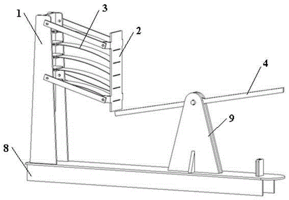
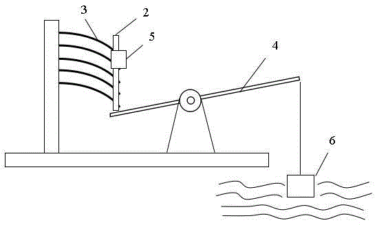
[0022] Specific implementation mode one: as Figure 1-2 As shown, the present invention provides a piezoelectric power generation device for capturing wave energy in the vertical direction, including a bracket 1, a clamping structure 2, a composite piezoelectric bistable plate 3 bonded with a piezoelectric material 7, a support arm 4, and a float 6. Support 8, base 9. The support 1 and the base 9 are fixed on the support 8, one end of the clamping structure 2 is fixed on the support 1, and the composite piezoelectric bistable plates 3 are clamped in parallel at equal intervals on the fixed end and the free end of the clamping structure 2 Above, a counterweight mass 5 is installed at the free end of the clamping structure 2, so that the composite piezoelectric bistable plate 3 is initially bent downward. The support arm 4 is used as a lever, the middle part is connected with the base 9, one end is tied with a float 6, and the other end is offset against the free end of the cla...

specific Embodiment approach 2

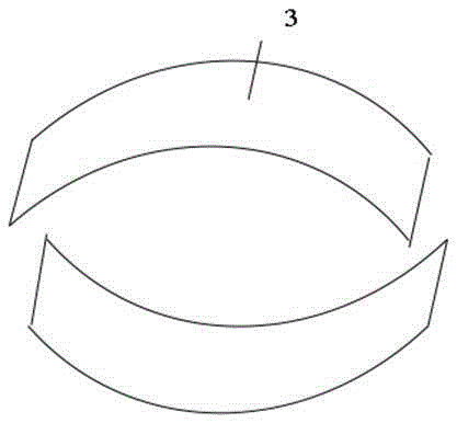
[0024] Embodiment 2: This embodiment provides a composite piezoelectric bistable plate, which is flat and rectangular before curing, and arc-shaped after curing. After curing, it has two stable shapes, such as image 3 As shown, the top is the first steady state, and the bottom is the second steady state. The composite piezoelectric bistable plate described in this embodiment adopts composite material and metal hybrid layering, solidifies at the curing temperature of the composite material, and can form an arc-shaped bistable effect due to residual thermal stress after cooling.

[0025] The layering is composed of symmetrical layering of composite materials and hybrid layering of metal composite materials, and both sides of the symmetrical layering of composite materials are hybrid layering layers of metal composite materials with symmetrical sizes.

[0026] Described composite material symmetrical layup is 90 ° and 0 ° composite material symmetrical layup, wherein 90 ° compos...

specific Embodiment approach 3

[0032] Specific implementation mode three: the specific layering method of the composite piezoelectric bistable plate in this implementation mode is as follows Figure 5 As shown, the upper part of the figure is the top view of the layup, and the lower part is the section view of the layup in different regions. The layup is divided into two regions, and the I region is a symmetrical layup of fiber composite materials, in which the 90° fiber composite material layer 10 is on the outside, and the 0° fiber composite material layer 11 is in the middle, such as [90 2 / 0 2 / 90 2 ]; II region is the metal fiber mixed region, the same 90 ° fiber composite material layer 10 is on the outside, and the metal Al layer 12 is in the middle, such as [90 2 / Al / 90 2 ]. It should be noted that in order to keep the thickness consistent, the thickness of the 0° fiber composite layer in the I region should be the same as that of the metal Al in the II region, and the 90° fiber composite layer ...


PUM


Abstract

The invention discloses a piezoelectric power generation device and method for capturing wave energy in the vertical direction. The piezoelectric power generation device comprises a support, a clamping structure, a composite piezoelectric bistable state plate with piezoelectric materials in a pasted mode, a support arm, a balance weight mass block and a floater, a frame and a base are fixed on the support, one end of the clamping structure is fixed on the frame, the other end of the clamping structure is the free end, the composite piezoelectric bistable state plate is clamped at the fixed end and the free end of the clamping structure, the middle of the support arm is hinged to the base, the floater is tied to one end of the support arm, one end of the clamping structure abuts against the free end of the clamping structure, and the balance weight mass block is installed at the free end of the clamping structure. By means of the piezoelectric power generation device and method, the function of converting wave energy in the vertical direction into electric energy is achieved; the piezoelectric power generation device has the advantages of being simple in implementation structure and is convenient to use, high in practicability and capable of providing the electric energy for a small low-power-dissipation load.

Description

technical field [0001] The invention belongs to the technical field of renewable energy power generation, and relates to an energy collection device and method, in particular to a device and method for collecting vertical wave energy in a piezoelectric manner. Background technique [0002] Wave energy is a kind of renewable energy ubiquitous on the earth. Scientific development and utilization are of great significance to alleviate energy crisis and environmental pollution. At present, a variety of wave energy technologies have been researched and developed in the world, most of which realize the collection of wave energy through energy conversion systems. CN102705147A discloses a wave energy conversion device comprising a flow guiding device, an impeller device, a thrust bearing, an energy conversion output unit, a buoyancy tank device and an anchoring device. CN102562424A discloses a wave energy capture device. Although the above-mentioned collection method has high effi...

Claims


Application Information

Patent Timeline
Patent Type & Authority Patents(China)
IPC IPC(8): H02N2/18
Inventor 戴福洪李昊潘殿坤
Owner HARBIN INST OF TECH
Why Eureka
Try Eureka