
Thin electronic ballast and manufacturing method of thin electronic ballast

A technology for electronic ballasts and manufacturing methods, applied to electric light sources, electrical components, lighting devices, etc., capable of solving problems such as additional breakage, poor contact or short circuit, complicated process, and increased manufacturing costs of electronic ballasts

Inactive Publication Date: 2014-10-01
DELTA ELECTRONICS INC
View PDF6 Cites 1 Cited by
  • Summary
  • Abstract
  • Description
  • Claims
  • Application Information

AI Technical Summary

Problems solved by technology

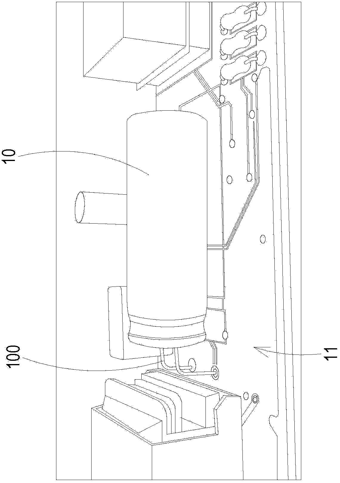
However, these methods have many disadvantages. One is that the design of the electronic components needs to be changed, which will greatly increase the manufacturing cost of the electronic ballast; figure 1 The design of relatively high electronic components, such as: capacitor 10, is designed as a horizontal molding, although it can reduce the overall height, but the horizontal capacitor 10 also takes up a large volume space, and then makes the circuit board 11 The usable space becomes smaller. In addition, the pin 100 of the capacitor 10 must also be bent in accordance with its horizontal design. In addition to the process of increasing the pin bending work, the design of the pin bending adds additional Possible breakage, poor contact or short circuit damage probability
In addition, in some existing technologies, in order to increase the usable space of the circuit board 11, a double-sided circuit board can be used to increase the space where electronic components can be placed, but this method will increase the cost even more.
[0004] In addition, some methods use thinner vertical transformers to reduce the overall height, but the leakage inductance of thinner vertical transformers will cause eddy current loss with the metal cover of the electronic ballast, so it is necessary to dispose of the transformer An additional insulating interlayer is set between the iron core and the circuit board, which will make the process more complicated and also easily increase the cost of manufacturing
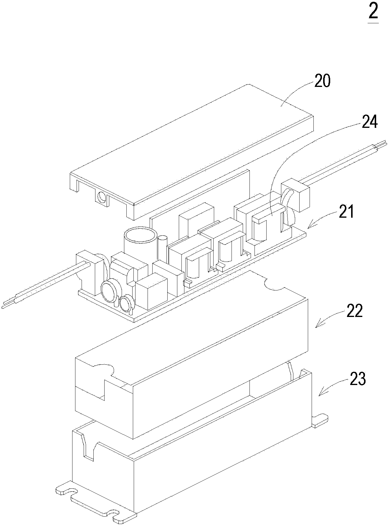
[0005] What's more, the above traditional technologies will all face the same problem in the manufacturing process, that is, if figure 2 As shown, when the circuit board 21 is to be arranged inside the electronic ballast 2, in order to effectively reduce the overall height, additional pressure must be applied to the circuit board 21 to push it down as much as possible. It is easy to expose the electronic components 24 on the circuit board 21 to the pins (not shown) on the lower surface of the circuit board 21 to pierce the insulating interlayer 22 for insulation and touch the metal shell 23, so in order to prevent the electronic components 24 from touching To the metal shell 23, in the traditional process, glue will be poured once, and after the metal shell 23 is filled with insulating glue for insulation and fixing, the circuit board 21 will be installed, and then the glue will be poured for the second time. After the gap between the plate 21 and the metal shell 23 is filled with insulating glue, the upper cover 20 is covered, so as to complete the process of the traditional electronic ballast 2, which shows that multiple times of glue filling operations are required in the process, and its manufacturing The steps are more complicated

Method used


Image

  • Thin electronic ballast and manufacturing method of thin electronic ballast
  • Thin electronic ballast and manufacturing method of thin electronic ballast
  • Thin electronic ballast and manufacturing method of thin electronic ballast

Examples


Embodiment Construction

[0047] Some typical embodiments embodying the features and advantages of the present invention will be described in detail in the description in the following paragraphs. It should be understood that the present invention can have various changes in different ways without departing from the scope of the present invention, and the descriptions and drawings therein are used for illustration in nature rather than for limiting the present invention .

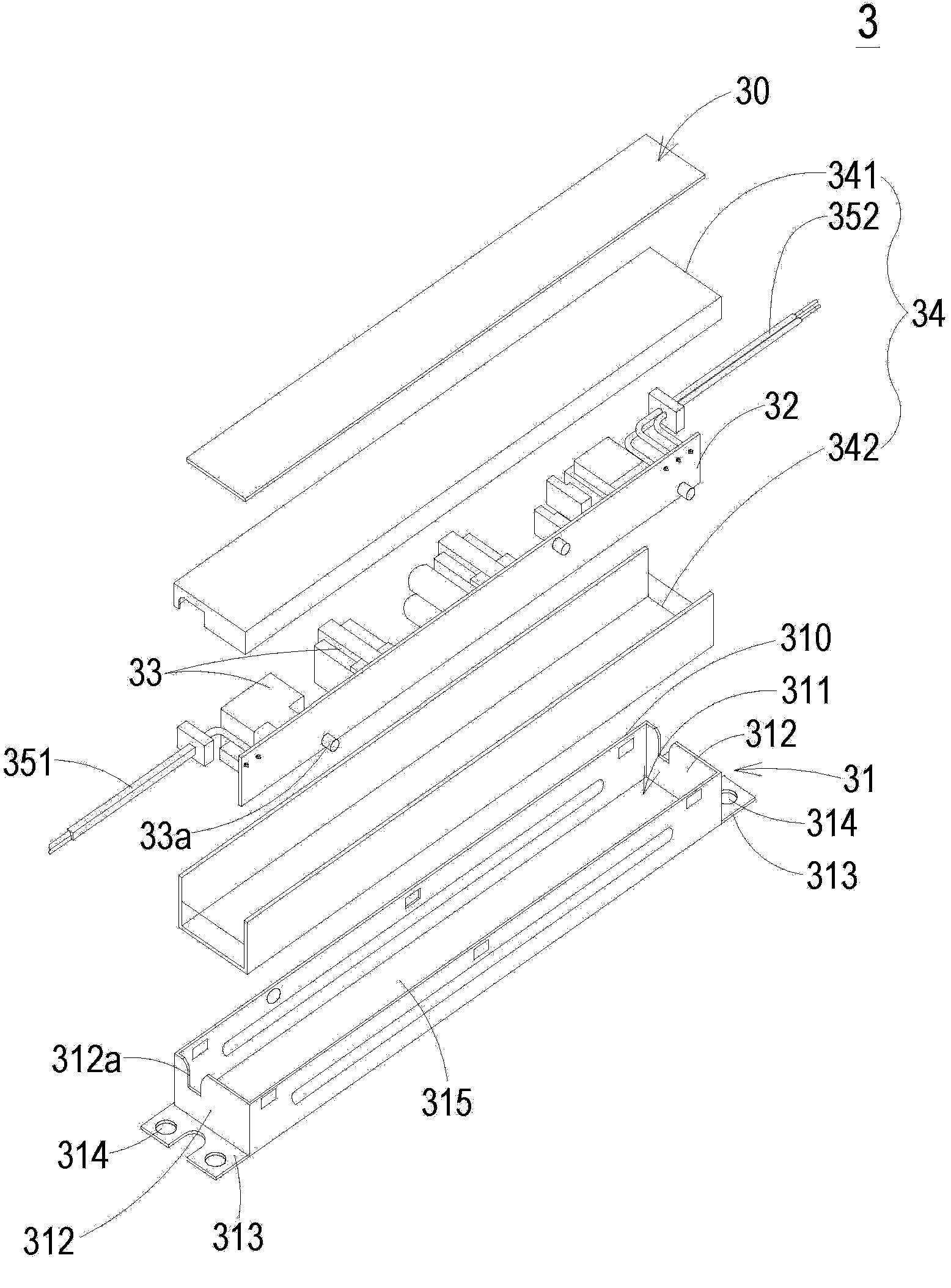
[0048] see image 3 , which is a schematic structural view of a thin electronic ballast according to a preferred embodiment of the present invention. As shown in the figure, the thin electronic ballast 3 of the present invention is composed of a metal shell 31, a circuit board 32, and a metal upper cover 30. The metal shell 31 has an opening 310 and an accommodating space 311, and the opening 310 It communicates with the accommodating space 311. The circuit board 32 is provided with a plurality of electronic components 33, and the...


PUM


Abstract

The invention discloses a thin electronic ballast, which is applicable to an illumination lamp and comprises a metal casing, a circuit board and a metal upper cover, wherein the metal casing is provided with an opening and an accommodating space; a plurality of electronic elements are arranged on the circuit board; and the metal upper cover correspondingly covers the opening of the metal casing, wherein the circuit board is arranged in the accommodating space of the metal casing and is arranged in a way of being perpendicular to the metal upper cover.

Description

technical field [0001] The invention relates to an electronic ballast, in particular to a thin electronic ballast capable of simplifying the process and reducing the cost and a manufacturing method thereof. Background technique [0002] The electronic ballast provides the starting voltage of the lighting fixture and provides a stable current to maintain the stability of the lighting. Therefore, for the lighting fixture, the product yield of the electronic ballast is extremely important. With the advancement of science and technology and the rapid development of electronic products, general daily necessities are also pursuing innovative and more convenient research and development. In the field of lighting fixtures, how to make lighting fixtures lighter and thinner so that their volume and weight are reduced, The smaller the occupied space, the more flexible the setting position is, which is the focus of active research and development in the relevant industries. In order to...

Claims


Application Information

Patent Timeline
IPC IPC(8): H05B41/02
Inventor 周清和
Owner DELTA ELECTRONICS INC
Learn More