

Inner wall machining machine tool and machining method
A technology for processing machine tools and bed, which is applied to inner wall processing machine tools and processing fields, can solve the problems of difficulty in guaranteeing manufacturing accuracy, increasing the feed rate per knife, and large deflection deformation of the tool bar, so as to avoid machining errors, high machining efficiency, The effect of speeding up processing
- Summary
- Abstract
- Description
- Claims
- Application Information
AI Technical Summary
Problems solved by technology
Method used
Image

Examples
Embodiment Construction
[0038] The technical scheme of the present invention will be described in detail below in conjunction with the accompanying drawings.
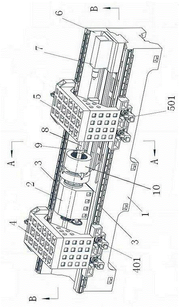
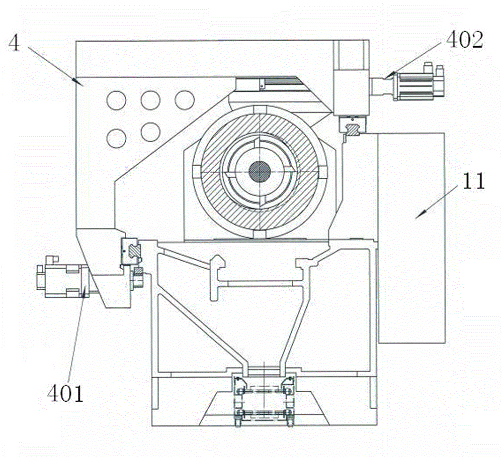
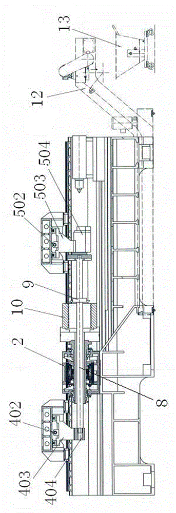
[0039] Such as Figure 1 to Figure 6 As shown, the inner wall processing machine tool of the present invention includes a bed 1, on which a headstock 2 and a guide rail 3 are installed, the direction of the guide rail 3 is parallel to the axial direction of the headstock 2, and the carriage II 4 is installed on the guide rail 3 And carriage I5, carriage I5 is located on the right side of headstock 2, carriage II4 is located on the left side of headstock 2, carriage II4 and carriage I5 can move left and right on bed guide rail 3.
[0040] When processing is required, first the workpiece 10 is installed on the chuck at the front end of the main shaft box 2 main shaft, then the tool 9 is installed on the middle part of the tool bar 8, and finally one end of the tool bar 8 passes through the center hole of the main shaft box 2 main shaft and is fi...
PUM
 Abstract
Description
Claims
Application Information