Liquid ejection head manufacturing method, liquid ejection head and printing device

A technology of a liquid ejection head and a manufacturing method, which is applied in the manufacture of liquid ejection heads, liquid ejection heads, and printing equipment, and can solve problems such as complex manufacturing processes and lower printing quality, and solve complex manufacturing processes, increase yield, and The effect of improving printing accuracy and printing quality

Active Publication Date: 2014-10-08
DALIAN UNIV OF TECH +1
View PDF5 Cites 10 Cited by
  • Summary
  • Abstract
  • Description
  • Claims
  • Application Information

AI Technical Summary

Problems solved by technology

[0005] The invention provides a method for manufacturing a liquid ejection head, a liquid ejection head and a printing device, which are used to solve the problems that the existing liquid ejection head manufacturing process is relatively complicated and the printing quality is easily reduced by using an adhesive

Method used


Image

  • Liquid ejection head manufacturing method, liquid ejection head and printing device
  • Liquid ejection head manufacturing method, liquid ejection head and printing device
  • Liquid ejection head manufacturing method, liquid ejection head and printing device

Examples


Embodiment Construction

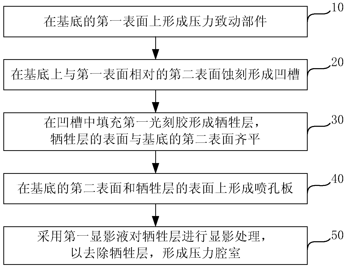
[0033] figure 1 A flow chart of a method for manufacturing a liquid ejection head provided by an embodiment of the present invention. Such as figure 1 As shown, the manufacturing method of the liquid jet head may include the following steps:

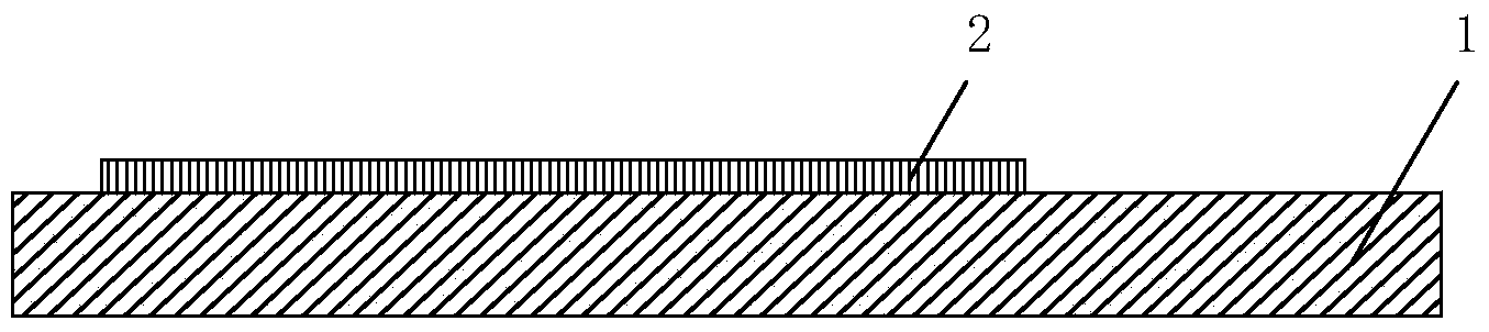
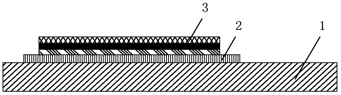
[0034] Step 10, forming a pressure actuated component on the first surface of the substrate.

[0035] The pressure actuation component can be a piezoelectric element or a thin film resistor commonly used in the prior art. If a piezoelectric element is used, the piezoelectric element is formed on the first surface of the substrate, and a voltage is applied through the piezoelectric element to deform the piezoelectric element, thereby applying pressure to the surrounding ink, so that the ink is ejected from the nozzle hole. On the printing medium; if a thin-film resistor is used, a thin-film resistor layer is formed on the first surface of the substrate, and a pulse voltage signal is applied to the thin-film resistor, and the thin-film ...


PUM


Abstract

The invention provides a liquid ejection head manufacturing method, a liquid ejection head and a printing device. The method comprises the steps that a pressure actuating part is formed on a first surface of a substrate; a groove is etched on a second surface opposite to the first surface on the substrate; the groove is filled with a first photoresist to form a sacrificial layer; the surface of the sacrificial layer is flush with the second surface of the substrate; orifice plates are formed on the second surface of the substrate and the surface of the sacrificial layer; and a first developer is used to develop the sacrificial layer to remove the sacrificial layer and form a pressure chamber. According to the liquid ejection head manufacturing method, the liquid ejection head and the printing device, which are provided by the invention, the problems that the manufacturing process of the existing liquid ejection head is complex, and the use of an adhesive easily reduces the printing quality are solved.

Description

technical field [0001] The invention relates to printer manufacturing technology, in particular to a method for manufacturing a liquid ejection head, a liquid ejection head and printing equipment. Background technique [0002] Printer is a commonly used office equipment. With the gradual advancement of printer technology, the speed of file processing and printing is getting more and more attention. The liquid ejection head is an important device in the printer. It prints ink drops on the printing medium by ejecting ink droplets to realize the printing process. The speed of ink droplets ejected by the liquid ejection head and the accuracy of the ejection position determine the printing speed of the printer and print quality. [0003] In order to achieve higher printing accuracy, a complex ink flow path is usually arranged inside the liquid ejection head, so that the ink can flow smoothly and accurately into corresponding channels. The existing liquid ejection head structure...

Claims


Application Information

Patent Timeline
Patent Type & Authority Applications(China)
IPC IPC(8): B41J2/16
CPCB41J2/1631B41J2/161B41J2/1623B41J2/1628B41J2/1629B41J2/1639B41J2/1642B41J2/1645B41J2/1646
Inventor 邹赫麟周毅孙莎
Owner DALIAN UNIV OF TECH
Why Eureka
Try Eureka