
A converter dehydration device capable of improving flue gas dehydration effect

A dehydration device and converter technology, applied in the manufacture of converters, etc., can solve the problems of insufficient space and position, and achieve the effects of saving upper and lower space, saving electricity, gas recovery benefits, and good steam-water separation effects

Active Publication Date: 2015-12-23
HEBEI IRON AND STEEL
View PDF6 Cites 0 Cited by
  • Summary
  • Abstract
  • Description
  • Claims
  • Application Information

AI Technical Summary

Problems solved by technology

[0004] The technical problem to be solved by the present invention is to provide a converter dehydration device that can improve the dehydration effect of flue gas. Electricity Effect and Improvement of Gas Recovery Benefit

Method used


Image

  • A converter dehydration device capable of improving flue gas dehydration effect

Examples


Embodiment Construction

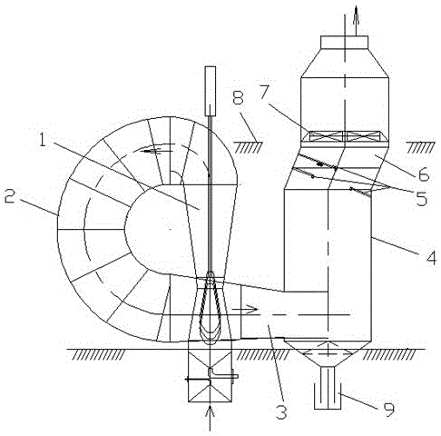
[0012] The invention breaks the traditional concept, and in order to overcome the problem of insufficient space, a swirl spray gun dehydrator is directly installed at the exit of the throat of the second-stage venturi tube to meet the dehydration effect of primary dust removal, realize the normal operation condition of the fan, and improve gas recovery power consumption and fan power saving effect.

[0013] The figure shows that when a normal dehydrator is installed, a vertically descending pipe greater than 4m is required at the outlet of the second-stage venturi tube 1, and then a vertically installed 15m dehydrator inlet is horizontally and tangentially connected, which requires 20m left and right and 25m up and down. space. In order to overcome the problem of insufficient installation space, the present invention designs a vortex steam-water separation pipeline 2 .

[0014] One end of the vortex steam-water separation pipe 2 is flange-connected to the throat of the second...


PUM


Abstract

The invention relates to a converter dewatering apparatus capable of increasing a dewatering effect of flue gas, and belongs to the technical field of converter dust-removing devices. The converter dewatering apparatus is used for increasing the dewatering effect of the flue gas. A technical solution lies in that the converter dewatering apparatus comprises a swirl spray gun dewaterer, a spray gun and a vortex steam-water separation pipe, wherein the vortex steam-water separation pipe is a bend pipe; one end of the vortex steam-water separation pipe is connected to a throat portion of a secondary venturi pipe; the other end of the vortex steam-water separation pipe is connected to the lower part of the swirl spray gun dewaterer. Under narrow installation space and position of a system device, the problem of insufficient space and position for installing the dewaterer normally can be overcome simply and practically and a dewatering effect of one dust removal can be met, by designing a swirl collector pipe and bend swirl spray gun dewaterer reasonably, thereby realizing normal operation of a draught fan under various conditions. The size of the throat circumferential seam of the secondary venturi pipe can be adjusted, so that the problem that the draught fan can not operate at low rotation speed is overcome; the air surge phenomenon is overcome; an electricity-saving effect is achieved; and flue gas recovery benefits are increased.

Description

technical field [0001] The invention relates to a dehydration device used for converter wet dust removal and flue gas treatment, and belongs to the technical field of converter dust removal equipment. Background technique [0002] In hot rolling production equipment, the converter is equipped with a wet dust removal device. The technological process of wet dedusting is: converter, vaporization cooling flue, spray tower, secondary venturi tube and throat, dehydrator, fan, three-way valve, water seal valve, V-shaped water seal, gas cabinet. Among them, the dehydration device is the main dehydration equipment for primary dust removal of the converter, and is the focus of the flue gas treatment working condition. It plays a key role in flue gas dehydration and is related to the system working condition and flue gas treatment effect. The dedusting water of the second-stage venturi tube comes out completely to ensure the various parameter requirements of the dedusting system. ...

Claims


Application Information

Patent Timeline
Patent Type & Authority Patents(China)
IPC IPC(8): C21C5/40C21C5/46
Inventor 许秋胜单立东王思源吴维杰吴立群杨晓江张文胜赵延军袁飞冯倩
Owner HEBEI IRON AND STEEL
Learn More