
Diaphragm type angular travel pneumatic actuating mechanism

A technology of pneumatic actuators and angular strokes, which is applied in the direction of engine components, mechanical equipment, valve details, etc., can solve the problems of difficult fitting between pneumatic actuators and valves, poor control accuracy, and low degree of cooperation, so as to improve rigidity, Guarantee the anti-seismic strength of the connection and the effect of low production cost

Active Publication Date: 2014-10-08
YANGZHOU ELECTRIC POWER EQUIP MFG FACTORY CO LTD
View PDF4 Cites 4 Cited by
  • Summary
  • Abstract
  • Description
  • Claims
  • Application Information

AI Technical Summary

Problems solved by technology

[0003] However, due to the differences in valve materials, manufacturing equipment, manufacturing processes, etc., and the performance of valves manufactured in different origins, there are also certain differences in performance; therefore, it is usually difficult to fit pneumatic actuators and valves. Large (output torque), poor control accuracy, low degree of coordination and poor compatibility

Method used


Image

  • Diaphragm type angular travel pneumatic actuating mechanism
  • Diaphragm type angular travel pneumatic actuating mechanism
  • Diaphragm type angular travel pneumatic actuating mechanism

Examples


Embodiment Construction

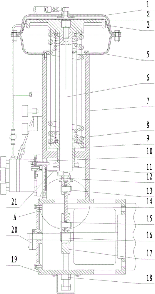
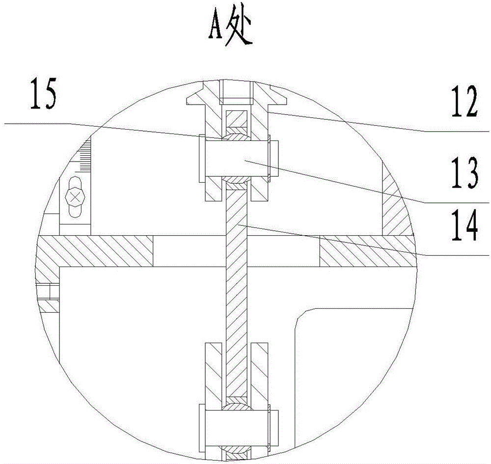
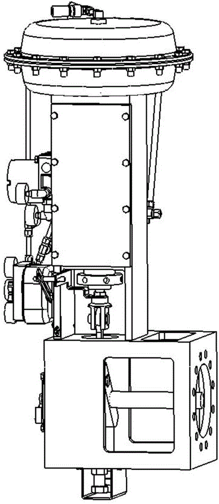
[0030] The invention as Figure 1-5 As shown, the valve stem 16 is used to drive the valve. The pneumatic actuator includes an upper housing 1, a lower housing 5, a push rod driving mechanism, a push rod 6, an upper frame 7, a lower frame 19, a linkage mechanism, and a feedback mechanism and limit position trigger mechanism;

[0031] The upper casing 1, the lower casing 5, the upper frame 7, and the lower frame 19 are fixedly connected sequentially from top to bottom, and the upper frame 7 includes an upper cavity and a lower cavity connected as one, and the upper cavity and the lower cavity There is a partition between them, and a threaded hole is opened in the middle of the partition;

[0032] The push rod 6 is arranged vertically and reciprocates up and down under the drive of the push rod driving mechanism. The upper end of the push rod 6 extends between the upper casing 1 and the lower casing 5, and the push rod 6 The lower end of the threaded hole extends out to the lo...


PUM


Abstract

The invention relates to the field of pneumatic actuating mechanisms and provides a diaphragm type angular travel pneumatic actuating mechanism which is ingenious in structure, good in comprehensiveness, high in matching degree, and capable of effectively fitting various specifications of angular travel valves in use so as to accurately control the opening degree and the output torque of the valves. The diaphragm type angular travel pneumatic actuating mechanism is used for driving a valve rod of a valve. The pneumatic actuating mechanism comprises an upper shell, a lower shell, a push rod driving mechanism, a push rod, an upper frame, a lower frame, a linkage mechanism, a feedback mechanism and a limit position trigger mechanism. The upper shell, the lower shell, the upper frame and the lower frame are fixedly connected in sequence from top to bottom, the upper frame comprises an upper cavity and a lower cavity which are connected into a whole, a partition plate is arranged between the upper cavity and the lower cavity, and a threaded hole is formed in the middle of the partition plate. The diaphragm type angular travel pneumatic actuating mechanism is simple in structure, low in production cost, capable of fitting in a torque characteristic curve of the valve, high in adjustment precision and good in adjustment effect.

Description

technical field [0001] The invention relates to the field of pneumatic actuators, in particular to the improvement of a nuclear-grade thin-film quarter-stroke pneumatic actuator. Background technique [0002] At present, the nuclear islands and conventional islands of my country's nuclear power plants mostly use quarter-turn valves, and these valves are controlled by pneumatic actuators. A representative example is a document titled "Nuclear Grade Membrane Pneumatic Actuator" with application number "201120374498.X" filed by the applicant on September 29, 2011. In this case, the applicant proposed A nuclear-grade membrane-type pneumatic actuator with simple structure, high shock resistance and easy installation is developed. [0003] However, due to the differences in valve materials, manufacturing equipment, manufacturing processes, etc., and the performance of valves manufactured in different origins, there are also certain differences in performance; therefore, it is usu...

Claims


Application Information

Patent Timeline
Patent Type & Authority Applications(China)
IPC IPC(8): F16K31/12
CPCF16K31/1262F16K37/0041
Inventor 蔡军徐文才朱乐尧张为费向军龚九洲郭庆韩松王召垒吴运国
Owner YANGZHOU ELECTRIC POWER EQUIP MFG FACTORY CO LTD
Learn More