

Toll station vehicle dynamic weighing estimation method and device
A dynamic weighing and estimating device technology, applied to measuring devices, weighing, instruments, etc., can solve the problems of slow measurement, damage to road pavement, and increase of road maintenance costs, so as to save time and improve traffic efficiency
- Summary
- Abstract
- Description
- Claims
- Application Information
AI Technical Summary
Problems solved by technology
Method used
Image

Examples
Embodiment Construction
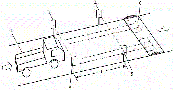
[0017] see figure 1 According to the present invention, the vehicle dynamic weighing and estimating device at the toll station includes a vehicle speed measuring module and a measuring impact force module. The vehicle speed measurement module is composed of a laser transmitter group and a photoelectric receiver group, which are respectively installed on the left and right sides of the toll station road. The laser transmitter group is composed of the first laser transmitter 2 and the second laser transmitter 4, the distance between the first laser transmitter 2 and the second laser transmitter 4 is L along the road length direction, and the photoelectric receiver group is composed of the first photoelectric receiver The device 3 is composed of the second photoelectric receiver 5, and the distance between the first photoelectric receiver 3 and the second photoelectric receiver 5 along the length direction of the road is also L. The first laser transmitter 2 is facing the firs...
PUM
 Abstract
Description
Claims
Application Information