Particle size analyzer

A particle size analyzer and particle technology, applied in the field of particle size analyzer, can solve the problem that the measurement range cannot cover the requirements of particle measurement, and achieve the effect of being easy to carry

Inactive Publication Date: 2014-10-08
UNIV OF SHANGHAI FOR SCI & TECH
View PDF5 Cites 24 Cited by
  • Summary
  • Abstract
  • Description
  • Claims
  • Application Information

AI Technical Summary

Problems solved by technology

[0015] The measurement range of the above-mentioned measuring instruments cannot cover the

Method used


Image

  • Particle size analyzer
  • Particle size analyzer

Examples


Embodiment 1

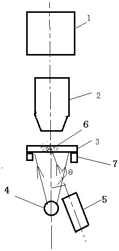
[0042] Embodiment 1: A particle size measuring device combining image method and dynamic light scattering, characterized in that the measuring device adopts an area array image sensor 1 as a measuring element, and a microscope objective lens is arranged under the area array image sensor 1 2. A sample cell 3 is placed on the focal plane of the microscope objective lens 2, and two light sources are placed under the sample cell 3, one of which is a transmission light source 4 using a light-emitting diode LED or a miniature bulb, and the transmission light source 4 is arranged In the axial direction of the sample cell 3 and the microscope objective lens 2, another scattered light source 5 using a laser is incident on the sample cell 3 at an angle of θ of 5-90 degrees; when measuring particles above microns, it is located in the sample cell 3 The transmitted light source 4 below emits illumination light to illuminate the measured particle sample 6 in the sample cell 3, the particle ...

Embodiment 2

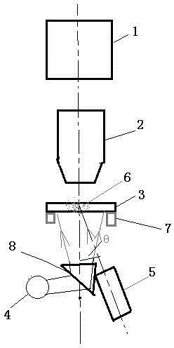
[0047] When considering the structural needs, the transmitted light source 4 is arranged at an angle with the optical axis of the sample cell 3 and the microscope objective lens 2.

[0048] At an angle of 90 degrees, the optical axis of the microscopic objective lens 2 and the light rays emitted by the transmission light source 4 are vertically intersected with a total reflection prism or reflector 8. The light is deflected by 90 degrees through the total reflection prism or mirror 8 to illuminate the particle sample on the sample cell. The particle image is enlarged and imaged on the image plane by the microscope objective lens 2, and the image signal obtained after the enlarged image is received by the image sensor 1 is sent to a computer for image processing to obtain the particle size distribution.

[0049] The sample pool 3 in the embodiment can be a cuvette or slide. The area array image sensor 1 in the embodiment can adopt CCD or CMOS device. The laser used for the sc...


PUM


Abstract

The invention discloses a particle size analyzer which is characterized in that a microscope objective is arranged below an area array sensor; a sample tank is arranged on the focusing plane of the microscope objective; two light sources, namely a transmission light source and a scattering light source are arranged below the sample tank; when micron-grade particles are measured, the transmission light source emits illumination light to illuminate particle samples to be detected, particle images are amplified by the microscope objective to be imaged on an image plane, and image signals obtained after receiving of the images by the area array sensor are transmitted to a computer to be processed to obtain particle size distribution; when nano particles are measured, the transmission light source is turned off while the scattering light source is turned on, laser emitted by the transmission light source is irradiated to nano particle samples, dynamic light scattering signals generated by Brownian movement of the nano particles are received by the area array sensor through the microscope objective, and the obtained signals are transmitted to the computer to be processed to obtain the particle size distribution. According to the particle size analyzer, the particles with the size range from nanometers to hundreds of microns can be measured by only one image sensor, so as to meet the requirements of wide-range particle measurement.

Description

[0001] technical field [0002] The invention relates to a particle size analyzer, in particular to a measuring device which realizes particle size measurement from nanometer to micron level based on the combination of image and dynamic light scattering measurement principles. [0003] Background technique [0004] Particle measurement methods There are many measurement principles and methods according to the particle size of the measured particles. For particles of micron size (from about 1 micron to hundreds of microns), the most important method is the laser particle size analyzer based on light scattering theory, in which the static scattered light of particles is measured. The basic principle is that when the laser is incident on the particle to be measured, the particle will scatter the incident laser light, and the spatial distribution of the scattered light energy is related to the size of the particle. Measure the spatial distribution of the scattered light energy,...

Claims


Application Information

Patent Timeline
IPC IPC(8): G01N15/02
Inventor 蔡小舒周骛
Owner UNIV OF SHANGHAI FOR SCI & TECH
Why Eureka
Try Eureka