Wideband printed miniature log periodic antenna

A logarithmic periodic antenna and broadband technology, applied in the field of ultra-wideband antenna miniaturization, can solve the problems of large logarithmic periodic antenna size and large printed circuit board size, and achieve the effect of increasing application space and reducing size

Active Publication Date: 2014-10-08
HARBIN INST OF TECH
View PDF3 Cites 6 Cited by
  • Summary
  • Abstract
  • Description
  • Claims
  • Application Information

AI Technical Summary

Problems solved by technology

[0003] The purpose of the present invention is to solve the problem that the size of the existing log-periodic antenna is too large, resulting in a larger size of the printed circuit board, and to provide a broadband printed miniaturized log-periodic antenna

Method used


Image

  • Wideband printed miniature log periodic antenna
  • Wideband printed miniature log periodic antenna
  • Wideband printed miniature log periodic antenna

Examples


specific Embodiment approach 1

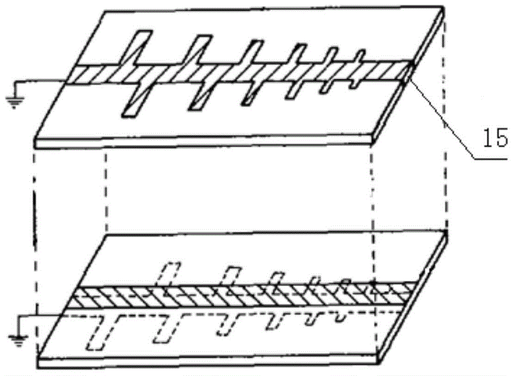
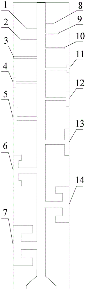
[0020] Specific implementation mode one: combine figure 1 and 2 Describe this embodiment, the broadband printing miniaturized logarithmic periodic antenna described in this embodiment, there are 14 elements on both sides of the feeder line of the logarithmic periodic antenna, and the seven elements on one side are in order from short to long The first array 1 to the seventh array 7, and the seven arrays on the other side are from the short array to the long array in turn from the eighth array 8 to the fourteenth array 14;

[0021] The first array 1, the second array 2, the third array 3, the eighth array 8, the ninth array 9 and the tenth array 10 are all in the shape of "one";

[0022] The fourth array 4, the fifth array 5, the eleventh array 111, the twelfth array 12 and the thirteenth array 13 are all "T" shapes;

[0023] No. 6 array 6, No. 7 array 7 and No. 14 array 14 are all in the shape of "mountain".

[0024] Such as figure 1 As shown, in order to make feeding more...

specific Embodiment approach 2

[0027] Specific implementation mode two: combination Figure 3 to Figure 6 , Figure 8 to Figure 11 Describe this embodiment. This embodiment is a further limitation of the broadband printed miniaturized log-periodic antenna described in Embodiment 1. In this embodiment, the width of the log-periodic antenna is 8.60 mm;

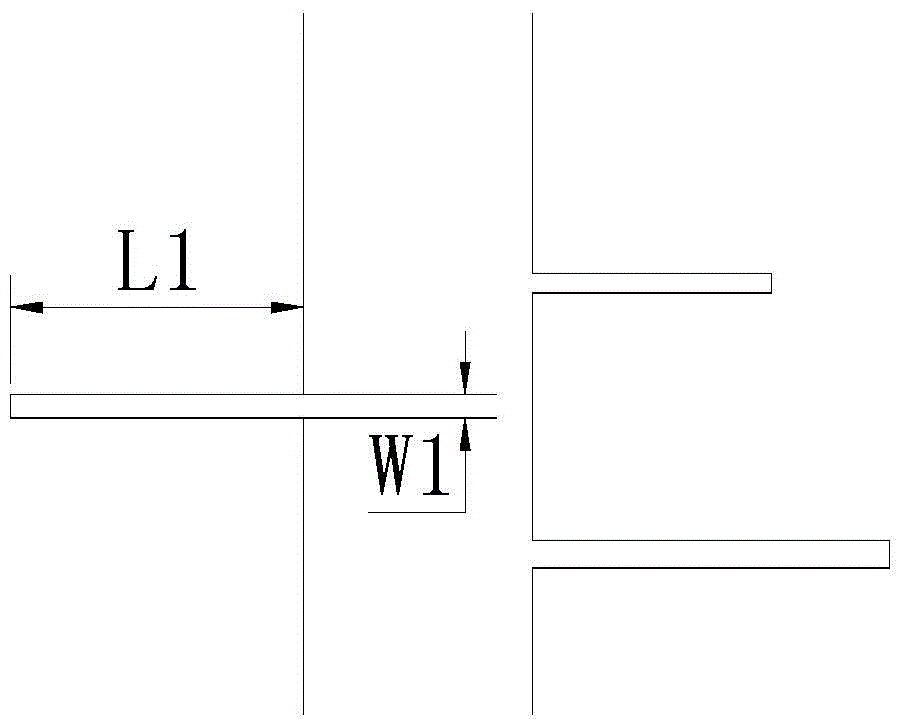
[0028] No. 1 array 1 is in the shape of "one", with a length of 1.66mm and a width of 0.13mm;

[0029] The second array 2 is in the shape of a "one" with a length of 2.46mm and a width of 0.19mm;

[0030] The third array 3 is in the shape of a "one" with a length of 3.61mm and a width of 0.28mm;

[0031] No. 4 element 4 is "T" shape, in the "T" shape, the length of the part perpendicular to the length direction of the feeder is 3.25mm, and the width is 0.4mm; the length of the part parallel to the length direction of the feeder is 1.62mm, and the width is 0.4mm;

[0032] The No. 5 element 5 is "T" shape. In the "T" shape, the length of the part perpendicu...

specific Embodiment approach 3

[0070] Specific implementation mode three: combination Figure 6 and Figure 7 Describe this embodiment. This embodiment is a further limitation of the broadband printed miniaturized log-periodic antenna described in Embodiment 1. In this embodiment, the centerline of the No. 1 array 1 to the log-periodic antenna The distance between the two short sides that are closer to it is 3.95mm, the distance from the center line of No. The distance in the direction is 4.68 mm.

[0071] Such as Figure 7 As shown, S01=3.95mm, S08=3.26mm. Such as Figure 7 As shown, S7=4.68mm.


PUM


Abstract

The invention discloses a wideband printed miniature log periodic antenna and relates to the ultra wideband antenna miniaturization technology. The wideband printed miniature log periodic antenna aims to solve the problem that an existing log periodic antenna is over large in size, and consequently a printed circuit board is large in size. The two sides of a feeder line of the antenna are provided with 14 arrays in total, wherein the seven arrays on one side are sequentially numbered from number one to number seven in the direction from the short arrays to the long arrays, and the seven arrays on the other side are sequentially numbered from number eight to number fourteen in the direction from the short arrays to the long arrays; the number one array, the number two array, the number three array, the number eight array, the number nine array and the number ten array are respectively in a line shape; the number four array, the number five array, the number eleven array, the number twelve array and the number thirteen array are respectively in a T shape; the number six array, the number seven array and the number fourteen array are respectively of an inverted-E shape. By means of optimizing the size of the antenna, the size can be reduced by over 50%, so that the size of the printed circuit board is greatly reduced. The wideband printed miniature log periodic antenna is suitable for wideband wireless transmission.

Description

technical field [0001] The invention relates to the miniaturization technology of an ultra-wideband antenna. Background technique [0002] The logarithmic periodic antenna was produced in the late 1950s. It is a type of frequency-invariant antenna based on the concept of "similarity". It has good broadband characteristics and is widely used in broadband wireless transmission. In the microwave band, it can be used as the illuminator of the reflector antenna or lens antenna, the radiation unit of the phased array antenna, etc.; in the ultrashort wave band, it can be used as a full-channel TV receiving antenna or applied to other broadband occasions; in the short wave band, it It is currently the only broadband antenna that can use one antenna to work in the entire short-wave band and maintain excellent electrical performance. As the frequency band we use continues to increase, the logarithmic periodic antenna is getting smaller and smaller, and the benefit it brings is that i...

Claims


Application Information

Patent Timeline
Patent Type & Authority Applications(China)
IPC IPC(8): H01Q1/38
Inventor 傅佳辉孙权崔健吕博陈晚
Owner HARBIN INST OF TECH
Why Eureka
Try Eureka