
Reactive power compensation protective device in power transmission and transformation system

A protection device, power transmission and transformation technology, applied in reactive power compensation, emergency protection circuit device, reactive power adjustment/elimination/compensation, etc., can solve the problem that the protection device cannot provide effective protection, the sensitivity of the protection device is not enough, and it cannot be realized Capacitor protection and other issues to achieve the effect of avoiding major failures, good social benefits, and improving power supply reliability

Inactive Publication Date: 2014-10-08
STATE GRID CORP OF CHINA +2
View PDF5 Cites 4 Cited by
  • Summary
  • Abstract
  • Description
  • Claims
  • Application Information

AI Technical Summary

Problems solved by technology

[0007] Although the open triangle and phase voltage differential have a certain response to the fault of the discharge coil, this protection method is mainly for the protection of low-voltage and small-capacity shunt capacitor banks.
[0008] In addition, each capacitor bank is composed of multiple capacitors connected in parallel. When a small number of capacitors fail, these types of protection devices have little impact on the overall capacitor bank, and the sensitivity of the protection device is not enough to achieve effective protection.
More importantly: the high-voltage shunt capacitor bank is the most important part of the reactive power compensation device, and its failure often starts from the capacitance change of a single capacitor, and all these current protection methods are aimed at serious failures that have already occurred The subsequent protection is aimed at the protection of the entire group of capacitors, and cannot be realized for each capacitor.
And often the failure starts from a single component, and the current protection devices cannot provide effective protection

Method used


Image

  • Reactive power compensation protective device in power transmission and transformation system

Examples


Embodiment Construction

[0025] Below in conjunction with accompanying drawing, the present invention will be further described by examples.

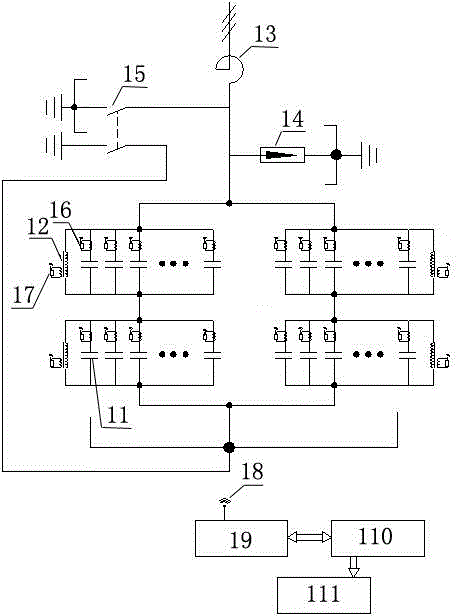
[0026] The embodiment is a main structural diagram of one phase of a 35kV reactive power compensation device. The high-voltage shunt capacitors are actually divided into two circuits, each with two strings. 11 in the figure is each capacitor, which is not separately distinguished, and 12 is Corresponding to the discharge coil of each series section, 13 is an air-core reactor, 14 is a lightning arrester, 15 is a grounding switch, 16 is a current unit installed on each capacitor, 17 is a secondary processing unit of the discharge coil 12, and 18 is a In the wireless transmission network, 19 is a background host, 110 is a protection node, and 111 is a substation protection system (relay protection system).

[0027] A protection device for reactive power compensation in a power transmission and transformation system, each single capacitor forms a capacitor branch c...


PUM


Abstract

The invention relates to a reactive power compensation protective device in a power transmission and transformation system, and belongs to the technical field of reactive power compensation in the power transmission and transformation system. The technical scheme is that a plurality of single capacitors (11) are connected in parallel to form string sections of high-voltage parallel capacitor groups; each string section is connected with a discharging coil (12) in parallel; a current unit (16) which contains a current sensor is arranged on each capacitor branch of each single capacitor; a background host processes received current signals of all the current units and received voltage signals of all the discharging coils, and transmits data to a protective module. According to the reactive power compensation protective device in the power transmission and transformation system, the sensitive protection on discharging coil failures and each capacitor can be realized; the most sensitive protection and failure warning on the high-voltage parallel capacitor groups can also be realized earliest; the reuse rate of reaction equipment is improved; the operation reliability of a reactive compensation device is improved; major failures are avoided as far as possible; the protection sensitivity is improved; failure equipment is cut in time; serious failures are avoided.

Description

technical field [0001] The invention relates to a protection device for reactive power compensation in a power transmission and transformation system, and belongs to the technical field of reactive power compensation in a power transmission and transformation system. Background technique [0002] In the power system, reactive power compensation is widely used, and it is the main form to improve the power factor of the grid, improve the voltage quality of the grid, and compensate the reactive power of the grid; with the continuous development of the grid, its transmission capacity continues to increase, and reactive power compensation As the demand increases, the main components of reactive power compensation devices: high-voltage and large-capacity capacitor banks are used more and more. However, operating experience shows that accidents such as bulging and explosion of high-voltage and large-capacity capacitor banks are not uncommon. For example, according to the statistica...

Claims


Application Information

Patent Timeline
Patent Type & Authority Applications(China)
IPC IPC(8): H02H7/16H02J3/18
CPCY02E40/30
Inventor 张建军王钰赵福旺孙红华袁燕岭张西术袁继军穆勇袁翔许文静李良杰李耐心程大印卢玉京赵玉文
Owner STATE GRID CORP OF CHINA
Learn More