Radio communication system, elevator control system, and electric power transformation equipment control system
A wireless communication system and signal technology, applied in elevator control system, substation equipment control system, and wireless communication system fields, can solve problems such as high possibility and difficulty in ensuring wireless communication reliability, and achieve the effect of reducing quality deterioration
- Summary
- Abstract
- Description
- Claims
- Application Information
AI Technical Summary
Problems solved by technology
Method used
Image

Examples
Embodiment 1
[0041] In this embodiment, a configuration example of a wireless device that performs wireless communication according to the present invention will be described.
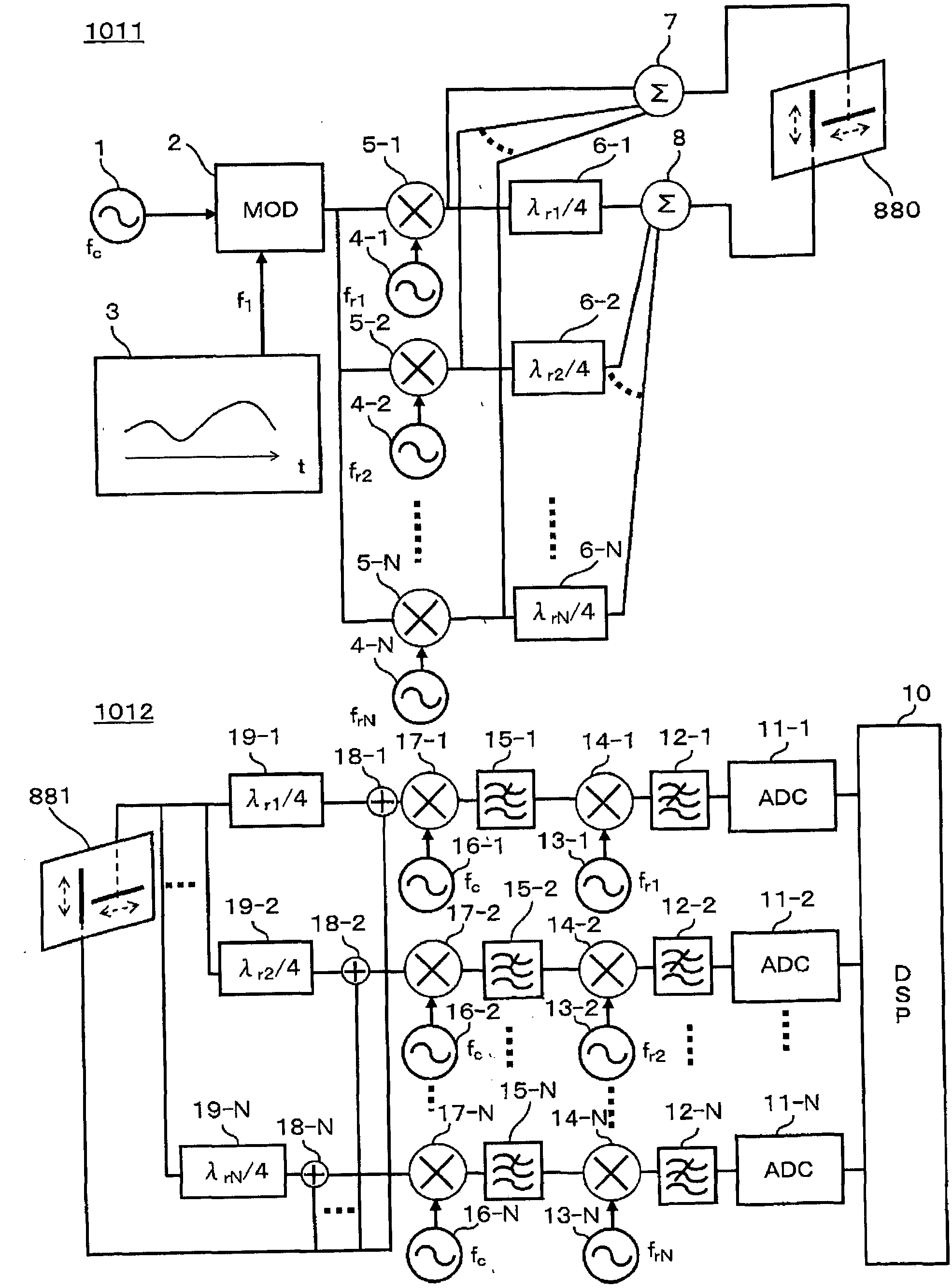
[0042] figure 1 It is an example of a configuration diagram of a transmitter and a receiver constituting the wireless communication system of this embodiment. In the transmitter 1011, a signal in the frequency band of frequency f1 is generated by the information signal generating circuit 3, and the carrier wave generated by the carrier generating circuit 1 is modulated by the modulator 2 using the signal. After the modulated signal is branched, it passes through a plurality of The transmission mixer 5 superimposes the sine waves of different rotational frequencies lower than the frequency of the carrier generated by the plurality of rotational signal generating circuits 4, and the superimposed signals are respectively divided into two branches, and one side of the divided signals is divided into two branches. Synt...
Embodiment 2
[0048] In this embodiment, another configuration example of a wireless device used in the wireless communication system of this embodiment will be described.
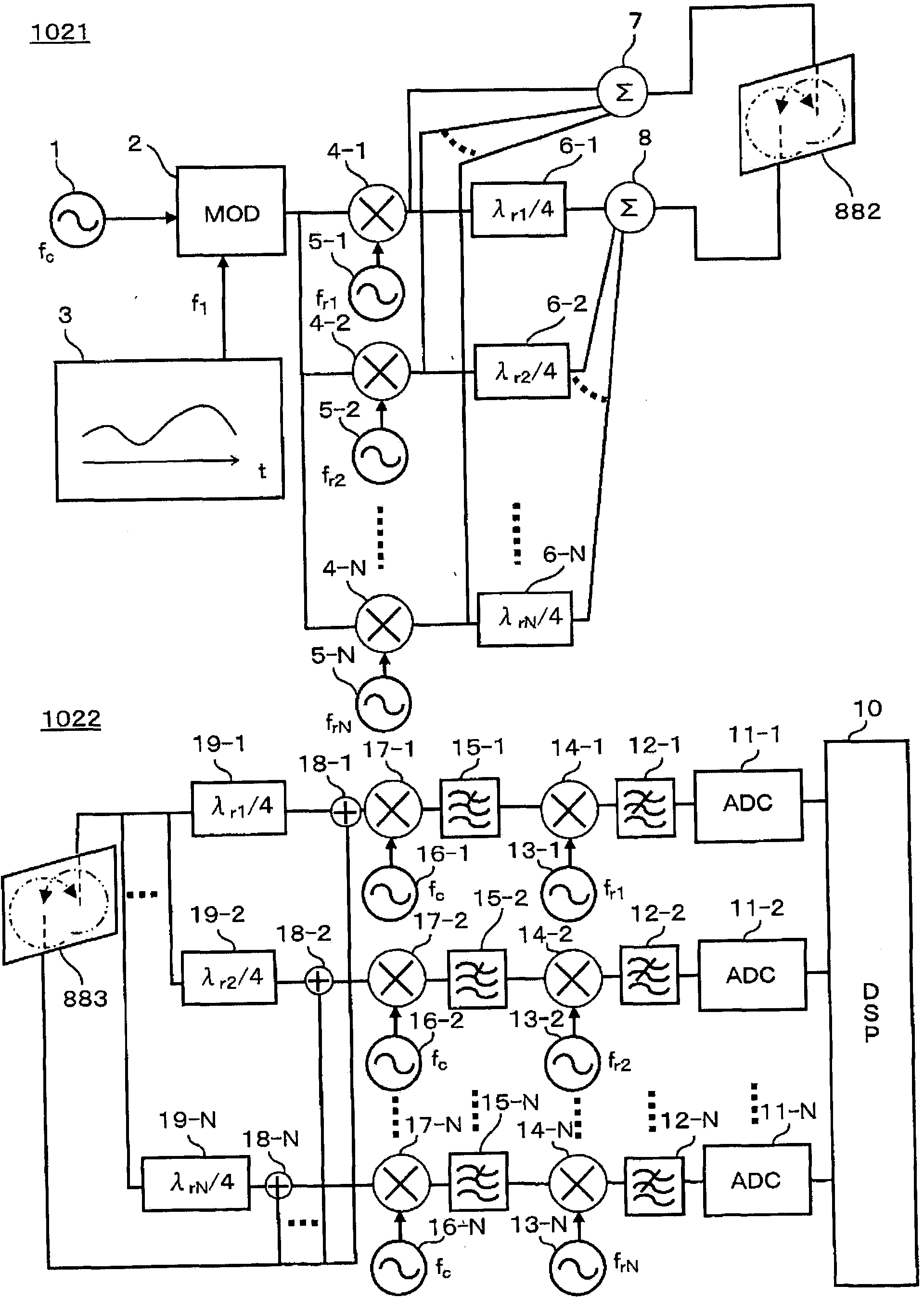
[0049] figure 2 It is an example of a configuration diagram of a transmitter and a receiver constituting the wireless communication system in the second embodiment. and figure 1 The embodiment differs in that a circular vertically polarized wave transmitting antenna 882 and an orthogonal vertically polarized wave receiving antenna 883 are used instead of the orthogonal vertically polarized wave transmitting antenna 880 and the orthogonal vertically polarized wave receiving antenna 881 .
[0050] That is, in this embodiment, the circular vertically polarized wave transmitting antenna 882 uses circularly polarized waves with different rotation directions to transmit to space the signal synthesized by the first transmission combining circuit 7 and the signal synthesized by the second transmitting combining circuit 8. si...
Embodiment 3
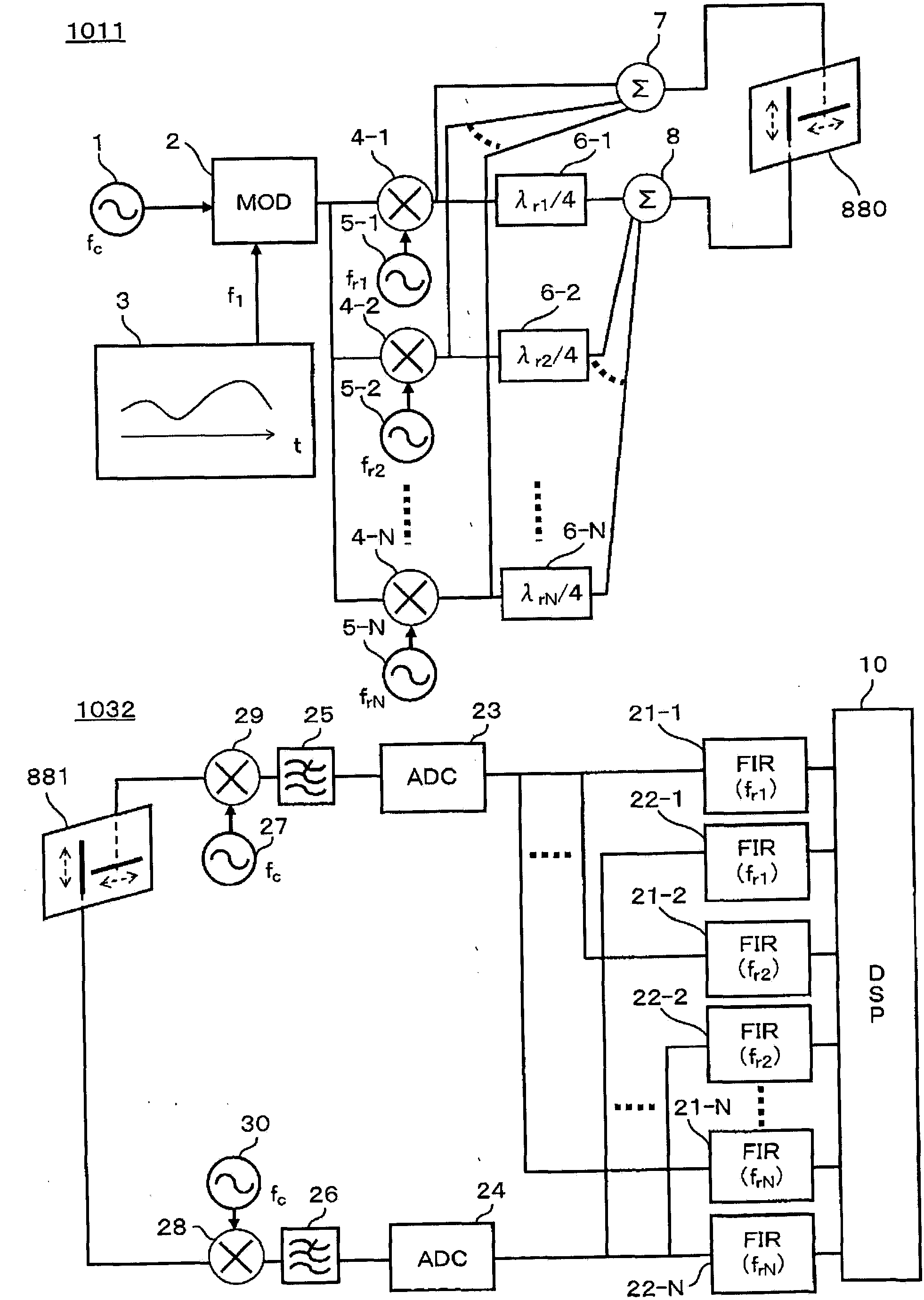
[0054] In this embodiment, another configuration example of a wireless device used in the wireless communication system of this embodiment will be described. image 3 It is an example of a configuration diagram of a transmitter and a receiver constituting the wireless communication system in the third embodiment.
[0055] and figure 1 The different points of the embodiments are: through the orthogonal vertically polarized wave receiving antenna 881, the receiver 1032 separates the received signal into different orthogonally polarized wave components for reception, and through the first receiving mixer 29, the One side of the separated received signal is multiplied by the output of the first local oscillator 27, wherein the first local oscillator 27 generates a sine wave of the same frequency as the carrier generation circuit 1, and the carrier frequency is removed by the first high-cut filter 25 The above frequency components are converted into digital signals by the first an...
PUM
 Abstract
Description
Claims
Application Information
 - R&D
- Intellectual Property
- Life Sciences
- Materials
- Tech Scout
- Unparalleled Data Quality
- Higher Quality Content
- 60% Fewer Hallucinations
Browse by: Latest US Patents, China's latest patents, Technical Efficacy Thesaurus, Application Domain, Technology Topic, Popular Technical Reports.
© 2025 PatSnap. All rights reserved.Legal|Privacy policy|Modern Slavery Act Transparency Statement|Sitemap|About US| Contact US: help@patsnap.com