
Electronic control device

A technology for electronic control devices and multilayer circuit substrates, applied in circuit devices, printed circuit grounding devices, printed circuits, etc., can solve the problems of not being able to use low-cost resin materials, achieve excellent reliability, and improve noise resistance Effect

Inactive Publication Date: 2014-10-08
HITACHI AUTOMOTIVE SYST LTD
View PDF9 Cites 6 Cited by
  • Summary
  • Abstract
  • Description
  • Claims
  • Application Information

AI Technical Summary

Problems solved by technology

[0010] However, in the prior art, since it is necessary to use a metal having a shielding effect for the frame, there is a problem that it is not possible to use an inexpensive material such as resin that transmits electromagnetic waves.

Method used


Image

  • Electronic control device
  • Electronic control device
  • Electronic control device

Examples


Embodiment Construction

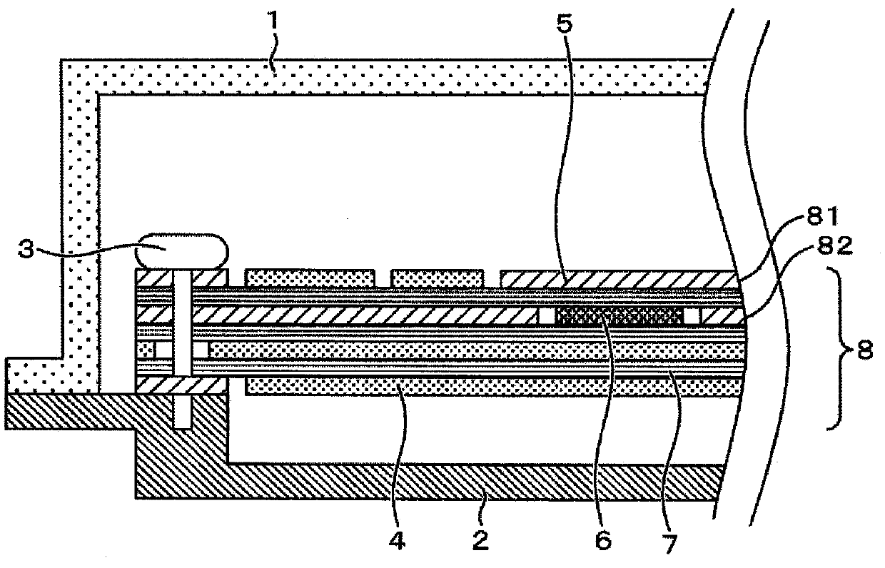
[0025] figure 1 It is a sectional view of the first embodiment of C / U in the present invention. Below, follow figure 1 to explain each symbol.

[0026] A multilayer circuit board 8 such as a glass epoxy board or a ceramic board is arranged in a space covered by the resin cover 1 and the metal base 2 , and electronic components (not shown) are mounted on both surfaces of the multilayer circuit board 8 . The electronic components mentioned here include: ICs, resistors, capacitors, inductors, and mechanical relays.

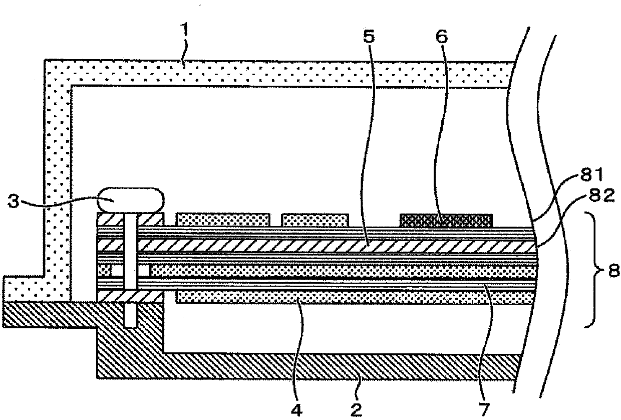
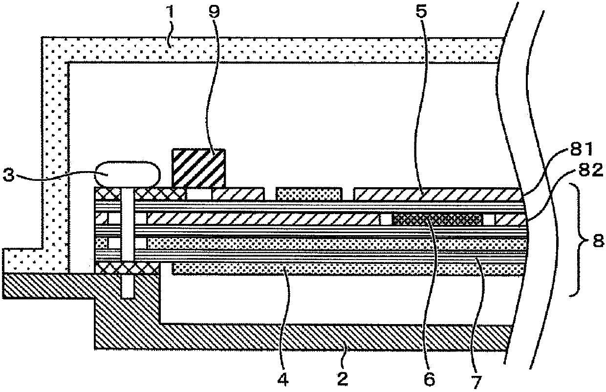
[0027] The multilayer circuit board 8 is composed of a signal pattern 4, a GND pattern 5, an important signal pattern 6, and a multilayer circuit board insulating layer 7, and is directly / indirectly connected to external circuits such as a power supply, a load, a sensor, and a switch. The signal pattern 4 mainly includes a power supply pattern, an overall power supply layer, an input circuit pattern, an output circuit pattern, and a circuit pattern for connectin...


PUM


Abstract

The purpose of the present invention is to provide a C / U structure having excellent reliability and enhanced noise resistance using an inexpensive structure. In order to achieve this purpose, there is provided a C / U having a resin cover (1) and a metal base (2), a multilayer circuit board (8) on which electronic components are packaged on both sides thereof being disposed so as to be covered by the resin cover and the metal base, the multilayer circuit board (8) comprising a signal pattern (4), a GND pattern (5), an important-signal pattern (6), and a multilayer circuit board insulating layer (7), and the GND pattern (5) being electrically connected to the metal base (2) through a screw (3), wherein the C / U is characterized in that the GND pattern (5) is disposed on the resin cover (1) side so as to shield the important-signal pattern (6); from electromagnetic waves that pass through from the resin cover (1) side and penetrate into a housing, or from electromagnetic waves radiated from the metal base (2) side, and the important-signal pattern (6) is disposed so as to be covered by the GND pattern (5) and the metal case (2).

Description

technical field [0001] The present invention relates to a vehicle-mounted electronic control device, and to a control device installed in an automobile, a marine machine, a farming machine, and a factory machine. Background technique [0002] In recent years, with the intensification of competition for cost reduction of electronic control devices (hereinafter, C / U) in the world, low-cost Designs in materials that are cheap and easy to prepare locally are on the rise. Although aluminum die-casting is used for the existing waterproof C / U housing, in recent years it has been changed to resin that is rich in formability and easy to manufacture in the world. [0003] On the other hand, the installation environment of C / U is deteriorating, and the requirements for electrical characteristics such as noise resistance and surge resistance are becoming stricter every year. Among noise resistance, it is necessary to design the C / U so that malfunction does not occur when the C / U is ir...

Claims


Application Information

Patent Timeline
IPC IPC(8): H05K9/00
CPCH05K2201/09336H05K1/0298H05K9/0039H05K1/0219H05K9/0064H05K5/006H05K1/0215H05K1/0218H05K1/0224H05K2201/10371
Inventor 角谷清臣石田良介黛拓也星野坚一冈田泰彦杉山泰志
Owner HITACHI AUTOMOTIVE SYST LTD
Learn More