Ethanol steam recycling tank

A technology of ethanol vapor and recovery tank, which is applied in the direction of steam condensation, chemical instruments and methods, separation methods, etc., which can solve the problems of poor condensation effect of heat exchangers, etc., and achieve the effect of effective condensation and recovery

Inactive Publication Date: 2014-10-15
ZHANGJIAGANG JIARUI PHARMA MACHINERY
View PDF7 Cites 4 Cited by
  • Summary
  • Abstract
  • Description
  • Claims
  • Application Information

AI Technical Summary

Problems solved by technology

[0002] At present, the condensation recovery of ethanol gas usually uses a common heat exchanger, but the condensation effect of the heat exchanger is poor, and the ethanol gas cannot be condensed and recovered efficiently.

Method used


Image

  • Ethanol steam recycling tank

Examples


Embodiment Construction

[0011] The present invention will be further described now in conjunction with accompanying drawing. These drawings are simplified schematic diagrams only to illustrate the basic structure of the present invention in a schematic way, so they only show the components relevant to the present invention.

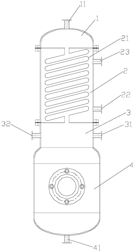
[0012] like figure 1 As shown, an ethanol vapor recovery tank has an air intake section 1 at the top, a condensation section 2, a vacuum section 3, and a recovery section 4 at the bottom. The top of the air intake section 1 is provided with an ethanol vapor inlet 11, and the condensation section 2 is provided with There is a spiral condenser pipe 21, the ethanol vapor outlet 11 at the bottom of the intake section 1 communicates with the inlet at the top of the spiral condenser pipe 21, the outlet at the bottom of the spiral condenser pipe 21 communicates with the vacuum section 3, and the lower part of the side wall of the condensation section 2 is provided with a condensed wate...


PUM


Abstract

The invention relates to an ethanol steam recycling tank. The recycling tank comprises a gas inlet section positioned at the top, a condensing section, a vacuum section, and a recycling section positioned at the bottom, wherein an ethanol steam inlet is formed in the top of the gas inlet section, a spiral condensing pipe is arranged on the condensing section, an ethanol steam outlet formed in the bottom of the gas inlet section is communicated with an inlet formed in the top of the spiral condensing pipe, an outlet formed in the bottom of the spiral condensing pipe is communicated with the vacuum section, a condensate water inlet is formed in the lower part of the side wall of the condensing section, a condensate water outlet is formed in the upper part of the side wall of the condensing section, a vacuum pumping opening and a gas supply opening are formed in the side wall of the vacuum section, and an ethanol recycling opening is formed in the bottom of the recycling section. The vacuum section is used for pumping the vacuum, the ethanol gas in the gas inlet section enters, and the ethanol gas enters the condensing section from the gas inlet section to be condensed into liquid ethanol to enter the recycling section at the bottom. By adopting the design of the gas inlet section, the condensing section, the vacuum section and the recycling section, the ethanol gas can be effectively condensed and recycled.

Description

technical field [0001] The invention relates to an ethanol vapor recovery tank. Background technique [0002] At present, common heat exchangers are usually used for the condensation and recovery of ethanol gas. However, the condensation effect of the heat exchanger is poor, and the ethanol gas cannot be condensed and recovered efficiently. Contents of the invention [0003] The technical problem to be solved by the present invention is to overcome the deficiencies of the prior art and provide an ethanol vapor recovery tank, which can effectively condense and recover ethanol gas. [0004] The technical scheme adopted by the present invention to solve the technical problem is: an ethanol vapor recovery tank, which has an air intake section at the top, a condensation section, a vacuum section, and a recovery section at the bottom, and the top of the air intake section is provided with ethanol vapor Inlet, the condensing section is provided with a spiral condensing pipe, the...

Claims


Application Information

Patent Timeline
Patent Type & Authority Applications(China)
IPC IPC(8): B01D5/00
Inventor 沈高峰吴敏娟邬亚兵季海熊杨小毅杨纯国任圣贤
Owner ZHANGJIAGANG JIARUI PHARMA MACHINERY
Why Eureka
Try Eureka