
Manufacturable metal-graphene interface for highly efficient and durable heat exchanger components

a technology of heat exchanger components and metal graphene, which is applied in the direction of indirect heat exchangers, refrigeration components, light and heating apparatus, etc., can solve the problems of poor heat conductivity of hydrophobic materials, waste of 50% or more energy, and inefficient heat transfer across condensing elements, so as to improve condensation efficiency and durability, and reduce maintenance costs. , the effect of improving energy efficiency

Active Publication Date: 2020-02-27
UNIVERSITY OF SOUTH CAROLINA
View PDF0 Cites 3 Cited by
  • Summary
  • Abstract
  • Description
  • Claims
  • Application Information

AI Technical Summary

Benefits of technology

The present patent is about improving heat exchanger components and methods of fabricating them. The invention involves coating the components with a metal or a combination of metal and carbon to enhance corrosion resistance and improve heat transfer efficiency. The coating can be applied to the entire surface or specific areas. The coating can help in efficient dropwise condensation, which can lead to improved energy efficiency and reduced maintenance costs. Overall, the invention provides durable and efficient heat exchanger components.

Problems solved by technology

Unfortunately, according to some estimates, condenser inefficiencies result in 50% or more wasted energy.
Regardless of the cause, the problem is inefficient heat transfer across the condensing elements.
One cause of inefficiency is simply the buildup of a layer of water on the surface of the condenser, which acts as an insulating element.
However, hydrophobic materials tend to be poor heat conductors and the efficiency gains made by adopting hydrophobic materials are negated by their reduced heat transfer ability.
However, most coatings tend to deteriorate quickly as they are not well suited for long-term operation in corrosive environments with high temperatures and steam.
Scale buildup and biofouling have also proven to be a significant source of condenser inefficiencies.
Of course, biofouling, scale buildup, and even the chemical treatment used to prevent these issues are detrimental to thin, hydrophobic condenser coatings, and further complicate the goal of achieving efficient heat transfer and dropwise condensation.
The seemingly simplistic nature of condenser function is deceiving as improving condenser efficiency in practice is a complicated problem that presents multiple challenges.

Method used


Image

  • Manufacturable metal-graphene interface for highly efficient and durable heat exchanger components
  • Manufacturable metal-graphene interface for highly efficient and durable heat exchanger components
  • Manufacturable metal-graphene interface for highly efficient and durable heat exchanger components

Examples


example 1

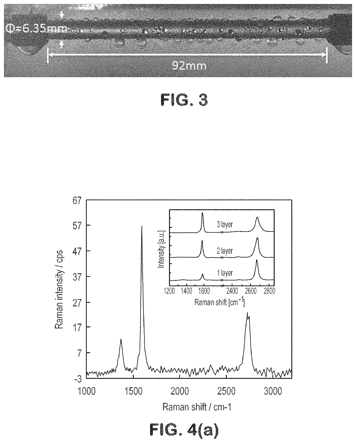
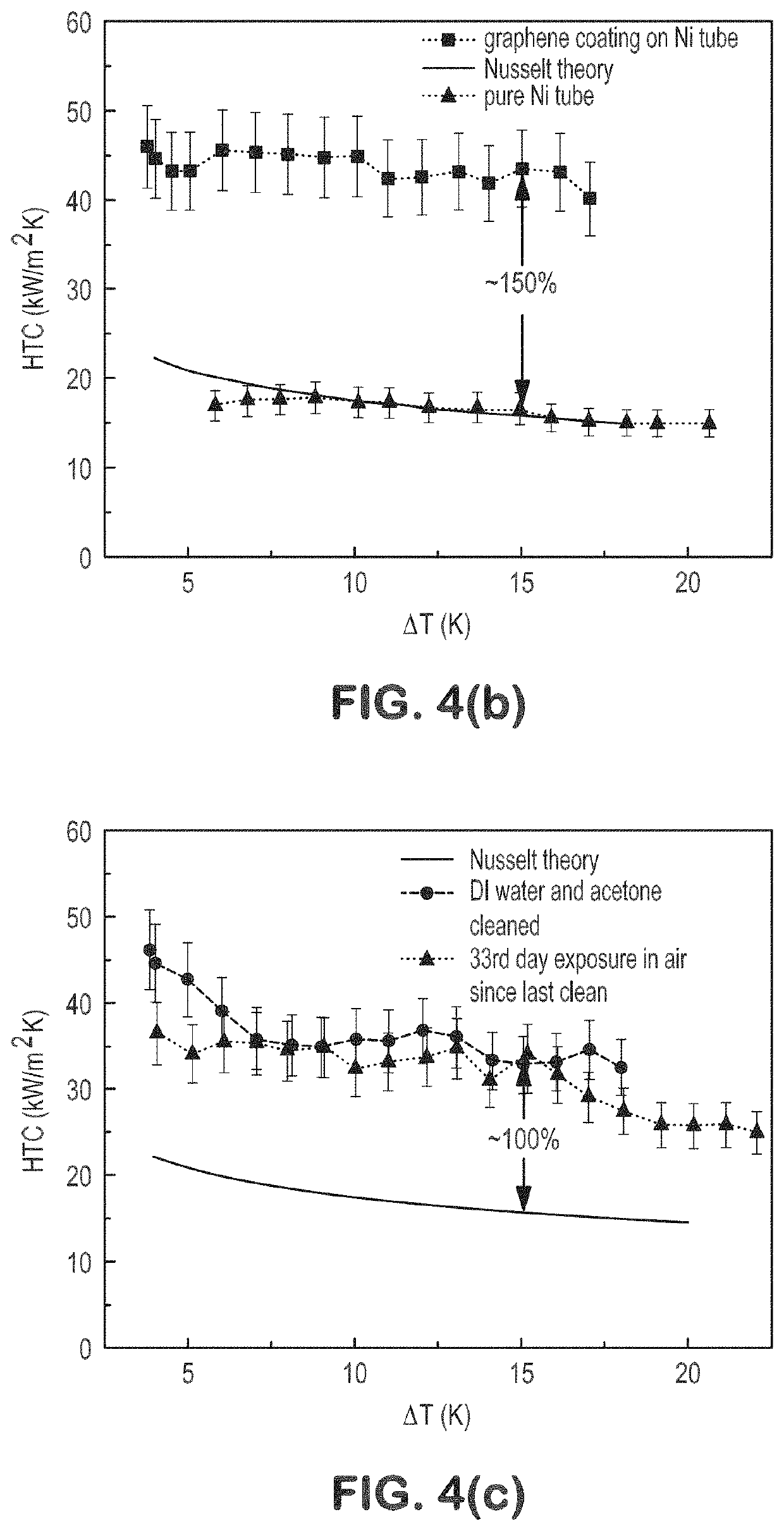
[0046]Nickel-graphene composite surfaces were produced. FIG. 4(a) shows a Raman spectroscopy graph for one, two, and three layers of graphene on a nickel substrate. FIG. 4(b) shows heat transfer coefficients (HTCs) of a pure nickel tube and a nickel tube having graphene layers. It can be seen that the nickel-graphene surface is able to produce approximately 150% greater heat transfer than the nickel tube without graphene. FIG. 4(c) shows HTCs after a period of 33 days. It shows that the nickel-graphene composite surface maintained superior heat transfer over the nickel only surface.

example 2

[0047]Both copper-graphene-monolayer and nickel-graphene-multilayer interfaces were prepared for steam condensation testing. Both surfaces were examined by X-ray photoelectron spectroscopy (XPS) before and after condensation experiments. As illustrated by FIG. 5(a), copper-graphene was oxidized after one two-hour test and quickly lost its graphene enhancement. In contrast, after a month-long test in air, the nickel-graphene composite did not show much oxidation, as seen in FIGS. 5(b), 5(c), and 5(d). The slight degradation in HTCs is likely due to the accumulation of hydroxyl groups (FIG. 5(b)), which increased with test time (FIG. 5(c)). This study shows that nickel-graphene interfaces exhibit superior anticorrosion properties in harsh steam environments. The superior durability of the nickel-graphene interface could be due to the similarities in thermal expansion between nickel and graphene. The thermal expansion mismatch between the graphene monolayer and the copper substrate is ...

example 3

[0049]Corrosion studies were performed using Tafel analysis. FIG. 7(a) shows the corrosion rates of copper-graphene interfaces and FIG. 7(b) shows the corrosion rates of nickel-graphene interfaces. As illustrated in FIG. 7(a), copper-graphene initially shows a low corrosion rate. However, once corrosion starts to occur locally, the corrosion rate begins to accelerate rapidly and globally. In contrast, and as illustrated in FIG. 7(b), the nickel-graphene interface is extremely stable and showed an approximately 450× lower corrosion rate even after a fourth test.

[0050]These and other modifications and variations to the present invention may be practiced by those of ordinary skill in the art, without departing from the spirit and scope of the present invention, which is more particularly set forth in the appended claims. In addition, it should be understood the aspects of the various embodiments may be interchanged both in whole or in part. Furthermore, those of ordinary skill in the a...


PUM

PropertyMeasurementUnit
thicknessaaaaaaaaaa
thicknessaaaaaaaaaa
thicknessaaaaaaaaaa

Abstract

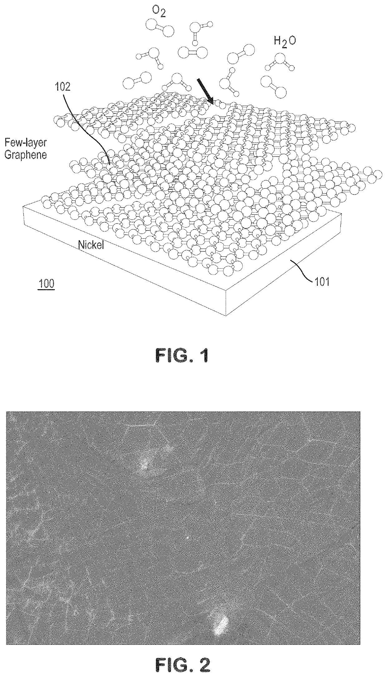
The present disclosure relates to efficient heat exchanger components, such as pipe apparatuses including the same. Methods of fabricating heat exchange components are also disclosed. A condensing apparatus can include a condenser surface having a substrate and one or more layers of graphene. The substrate can be formed of nickel and a nickel-graphene surface composite layer can be formed. The substrate-graphene composite can be highly durable, hydrophobic, and resistant to fouling. Dropwise condensation can be induced.

Description

PRIORITY INFORMATION[0001]The present application is a continuation in part of U.S. patent application Ser. No. 16 / 217,100, filed on Dec. 12, 2018, which claims priority to U.S. Provisional Patent Application Ser. No. 62 / 607,154, filed on Dec. 18, 2017, the entire disclosures of which are incorporated by reference herein.GOVERNMENT SUPPORT[0002]The subject invention was made with government support under a research project supported by the National Science Foundation Grant No. 1357920. The government has certain rights in the invention.BACKGROUND[0003]Heat exchanger components, such as condensers, are important to many industries. For example, condensers are widely used in the petrochemical industry, as well as for water purification, desalination, and power generation. In power generation, steam is made from heat generated by fossil fuels or other sources. The steam generation creates high pressures and the steam flows through a turbine to a lower pressure area and eventually colle...

Claims


Application Information

Patent Timeline
Patent Type & Authority Applications(United States)
IPC IPC(8): F28D15/04F28F21/02F28F21/08
CPCF28F21/089F28D15/046B23P15/26F25B2339/04F28F2245/02C23C16/26F28F21/02F28F13/182F28F13/187C23C16/0281
Inventor LI, CHENCHANG, WEIPENG, BENLIWANG, PENGTAO
Owner UNIVERSITY OF SOUTH CAROLINA
Learn More