Particle concentration electro-turbulent coagulation device for PM2.5 removal

A particle and density technology, applied in the field of particle density and electric turbulent coagulation devices, can solve the problems of difficult operation, large water consumption, low reliability, etc., and achieve good development prospects, good theoretical innovation, and convenient operation.

Active Publication Date: 2018-07-27
XI AN JIAOTONG UNIV
View PDF5 Cites 3 Cited by
  • Summary
  • Abstract
  • Description
  • Claims
  • Application Information

AI Technical Summary

Problems solved by technology

This method has a lot of equipment, complex structure, low reliability, consumes a lot of water resources and requires anti-corrosion treatment of the equipment, so the cost is high and the operation is difficult

Method used


Image

  • Particle concentration electro-turbulent coagulation device for PM2.5 removal
  • Particle concentration electro-turbulent coagulation device for PM2.5 removal
  • Particle concentration electro-turbulent coagulation device for PM2.5 removal

Examples


Embodiment 1

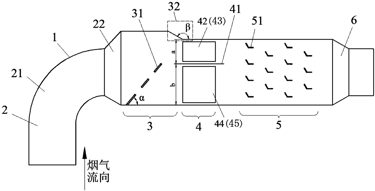
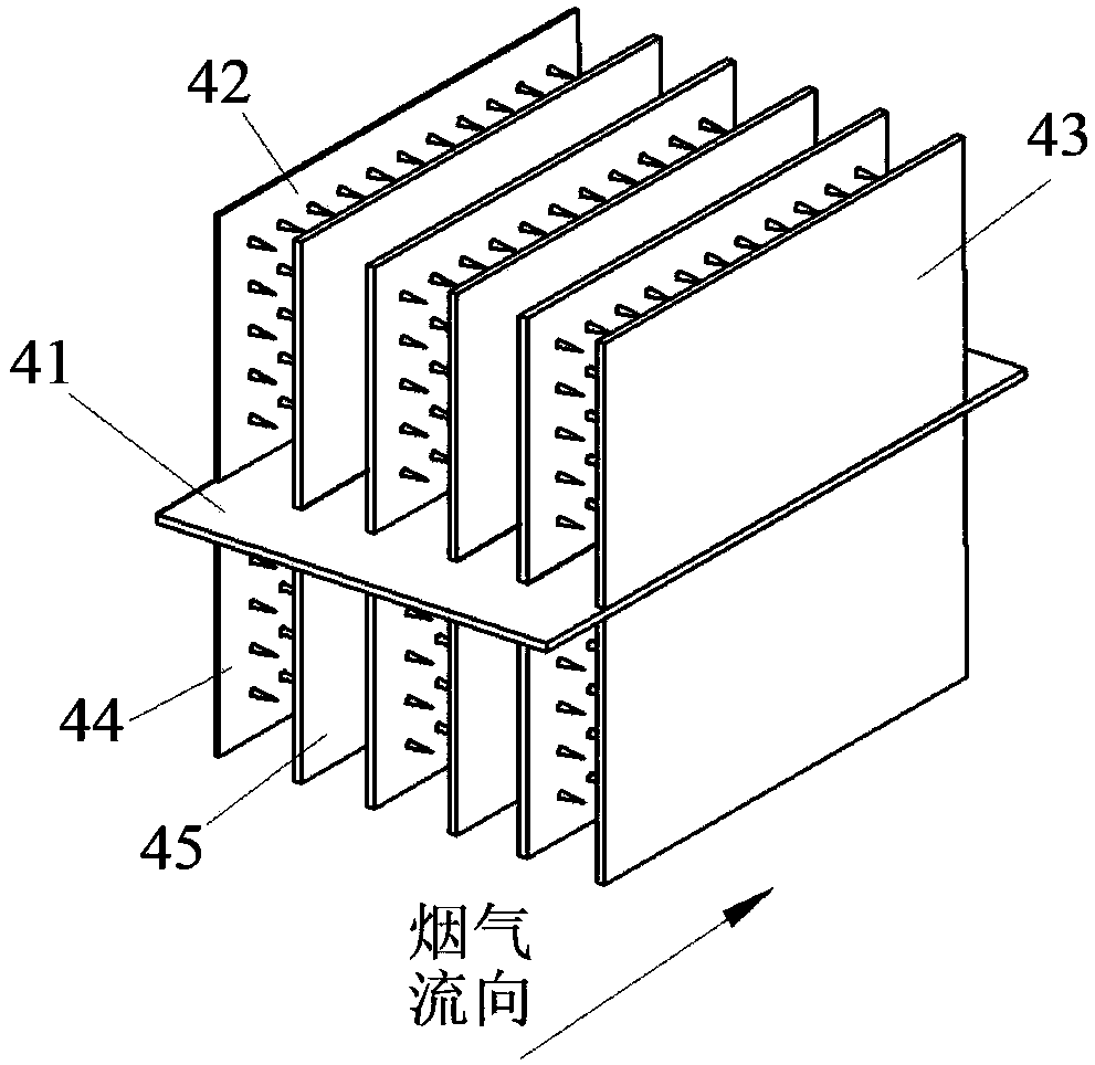
[0039] like figure 1 As shown, the main structure of the device of the present invention includes a housing 1 preferably with a rectangular cross-section, an inlet diverging section 2 , a thick-thin separation section 3 , a heteropolar charging section 4 , a turbulent flow condensation section 5 and an outlet tapering section 6 . The inlet gradual expansion section 2 is composed of a constant cross-section flow channel 21 and a gradual expansion cross-section flow channel 22, wherein the constant cross-section flow channel 21 is an elbow structure, which can make the fine particles flow due to the centrifugal force and initially realize the separation of thick and thin, which is beneficial to Enhance the condensation effect of PM2.5. The thick-thin separation section 3 includes a louver baffle 31 composed of 4 plane baffles located on the same plane. The baffle and the flue gas flow form an inclination angle of α=45°, and a certain gap is left between adjacent baffles. The baf...

Embodiment 2

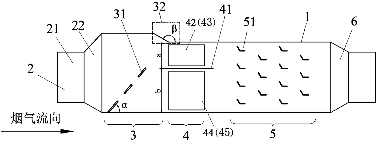
[0041] like figure 2 As shown, the inlet diverging section 2 of the device of the present invention is composed of a constant cross-section flow channel 21 and a diverging cross-section flow channel 22, wherein the constant cross-section flow channel 21 is a straight pipe structure. Particles in the flue gas enter the device through the constant cross-section flow channel 21, and the flow velocity is reduced through the gradually expanding cross-section flow channel. Further, after the flue gas particles pass through the louver 31 of the thick-thin separation section 3, two dust-laden airflows, thick and thin, are qualitatively formed, and the airflow with a higher particle concentration passes through the converging angle 32 to further increase the concentration of particles. The separation baffle 41 in the heteropolar charging section 4 quantitatively divides the dust-laden airflow into thick and thin dust-laden airflows, and most of the PM2.5 is located in the dust-laden a...


PUM


Abstract

The invention discloses a particle concentration electro-turbulent coagulation device for PM2.5 removal, wherein the device has high coagulation efficiency, convenient operation and high adaptability,and is convenient to popularize and apply. The particle concentration electro-turbulent coagulation device includes an outer shell having a flue gas channel formed inside the outer shell, the interior of the outer shell is provided with an inlet gradual enlargement section, a thick and diluted separation section, a heteropolar charged section, a turbulent coagulation section and an outlet gradualshrinkage section along the flow direction of flue gas successively; the thick and diluted separation section is used for separating the dust-containing flue gas containing a large amount of PM2.5 toform a thick dust-containing gas flow and a diluted dust-containing gas flow with different particle concentrations. The heteropolar charged section is used for charging the thick dust-containing flue gas and the diluted dust-containing flue gas with different particle concentrations, and particles in the low-concentration particle zone can be charged with heteropolar charge with opposite polarity of particles in the high-concentration particle zone; the turbulent coagulation section contains a number of turbulent flow elements arranged in an aligned or staggered arrangement and made of fluoroplastics, and each turbulent flow element consists of two flat plates having a certain included angle gamma of 120-160 degrees and forming an L shape.

Description

technical field [0001] The invention relates to the technical field of particulate matter emission control in the coal-burning industry, in particular to a particle density electric turbulent coagulation device for PM2.5 removal. Background technique [0002] In recent years, my country's smog pollution has been serious, affecting people's normal life, work, and physical and mental health. One of the main reasons is the emission of coal-fired flue gas particles, especially fine particles (particles with a kinetic diameter less than 2.5 μm, that is, PM2.5) . The PM2.5 emitted by the coal-fired industry has a long residence time and long-distance transportation capacity due to its light weight and small particle size, and it is easy to react with air pollutants twice to cause more serious environmental pollution, and can even pass through the alveoli of the human body Enter the blood circulation system, and then seriously endanger human health. At present, my country's tradit...

Claims


Application Information

Patent Timeline
Patent Type & Authority Applications(China)
IPC IPC(8): B01D50/00B03C3/017
CPCB01D50/00B03C3/0175
Inventor 谭厚章刘鹤欣张思聪杜勇乐
Owner XI AN JIAOTONG UNIV
Why Eureka
Try Eureka