A turn-back type air pollutant elimination device
An air pollutant and reentrant technology, applied in the direction of combined devices, heating methods, air conditioning systems, etc., can solve the problem of large amount of central air conditioning renovation, and achieve the effect of low cost, low energy consumption, and small volume
- Summary
- Abstract
- Description
- Claims
- Application Information
AI Technical Summary
Problems solved by technology
Method used
Image
Examples
Embodiment 1
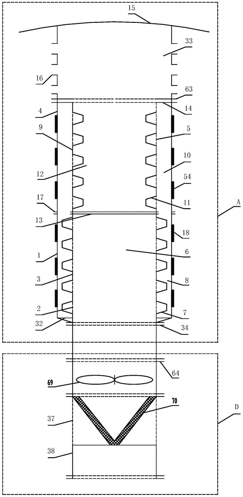
[0026] figure 1 It is the reentrant air pollutant elimination device applied to the air source heat pump device provided by this embodiment, which includes the first reentrant air pollutant filter adsorption device A applied to the air source heat pump device D. The structure of the first turn-back air pollutant filtering and adsorbing device A is that a first inner layer air duct 2 is arranged inside the first outer layer air duct 1, and the first outer layer air duct 1 is connected to the second air duct 1 through the first flange 17. The outer layer air duct 4, the second inner layer air duct 5 is arranged inside the second outer layer air duct 4, and the first blocking plate 13 is arranged at the adjacent end of the first inner layer air duct 2 and the second inner layer air duct 5 , the coarse-effect filter chamber 6 is formed in the first inner layer air duct 2, the cavity between the first outer layer air duct 1 and the first inner layer air duct 2 forms a coarse-effect...
Embodiment 2
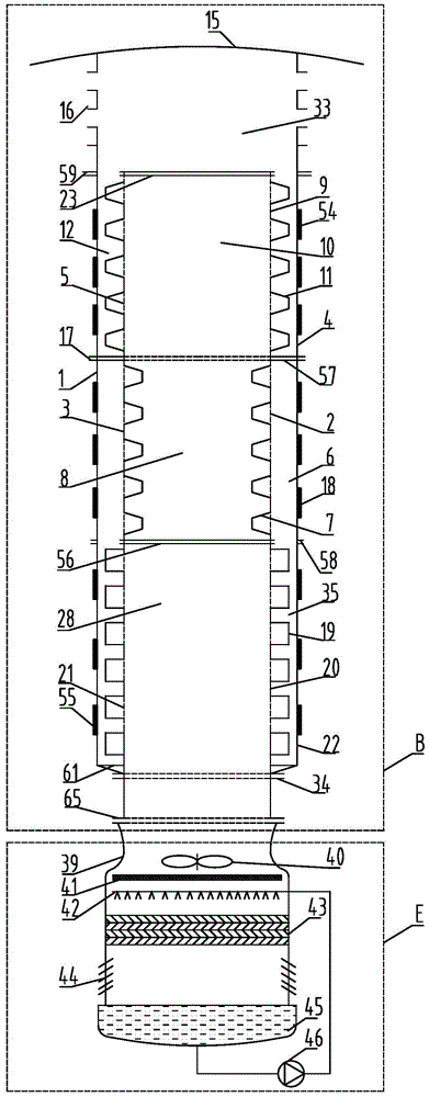
[0031] figure 2 It is the turn-back type air pollutant elimination device applied to the spraying device of the cooling tower provided by this embodiment, which includes the second turn-back type air pollutant filtering and adsorbing device B applied to the spraying device E of the cooling tower. The structure of the second turn-back air pollutant filtering and adsorbing device B is that a third inner layer air duct 21 is arranged inside the third outer layer air duct 22, and the third outer layer air duct 22 is connected to the first air duct through the fifth flange 58. The outer layer air duct 1, the first inner layer air duct 2 is arranged inside the first outer layer air duct 1, and the fourth blocking plate 56 is arranged at the end adjacent to the third inner layer air duct 21 and the first inner layer air duct 2 , the activated carbon adsorption chamber 28 is formed in the third inner layer air duct 21, the cavity between the third outer layer air duct 22 and the thir...
Embodiment 3
[0037] image 3It is the reentrant air pollutant elimination device applied to the fan muffler provided in this embodiment, which includes a third reentrant air pollutant filter adsorption device C applied to the fan muffler F. The structure of the third reentrant air pollutant filtering and adsorbing device C is that a first inner layer air duct 2 is arranged inside the first outer layer air duct 1, and the first outer layer air duct 1 is connected to the third air duct 1 through the fifth flange 58. The outer layer air duct 22, the third inner layer air duct 21 is arranged inside the third outer layer air duct 22, and the fourth blocking plate 56 is arranged at the adjacent end of the first inner layer air duct 2 and the third inner layer air duct 21, The inside of the first inner layer air duct 2 constitutes a coarse-effect filter chamber 6, the cavity between the first outer layer air duct 1 and the first inner layer air duct 2 forms a rough-effect purification chamber 8, ...
PUM
 Abstract
Description
Claims
Application Information
 - R&D
- Intellectual Property
- Life Sciences
- Materials
- Tech Scout
- Unparalleled Data Quality
- Higher Quality Content
- 60% Fewer Hallucinations
Browse by: Latest US Patents, China's latest patents, Technical Efficacy Thesaurus, Application Domain, Technology Topic, Popular Technical Reports.
© 2025 PatSnap. All rights reserved.Legal|Privacy policy|Modern Slavery Act Transparency Statement|Sitemap|About US| Contact US: help@patsnap.com


