Rolling cutter bit

A technology of rolling knives and blade bodies, applied in the field of machining parts, can solve the problems of uneven force on the rolling surface, inconsistent hardness of the machined surface, unable to meet the requirements of the drawings, etc., so as to improve the machining accuracy, overcome the tool setting error, simple structure

Inactive Publication Date: 2014-10-15
NANJING HAOWEI MACHINERY
View PDF0 Cites 13 Cited by
  • Summary
  • Abstract
  • Description
  • Claims
  • Application Information

AI Technical Summary

Problems solved by technology

[0006] 1) In terms of processing methods: due to human error when clamping the rolling knife, the rolling wheel may not be perpendicular to the rolling surface when setting the knife, resulting in insufficient force on the rolling surface during the rolling process. uniform, so that the rolling roughness is not very stable, and sometimes it cannot meet the requirements of the drawing
[0007] 2) In terms of processed parts: the surface roughness of the part surface can reach a high level under the previous fine turning process, but there are also defects that cannot be avoided. There may also be some surface roughness caused by the local hardness of the part material. The hardness is inconsistent, which makes it impossible to obtain better roughness under rolling

Method used


Image

  • Rolling cutter bit

Examples


Embodiment Construction

[0016] The present invention will be further explained below in conjunction with the accompanying drawings.

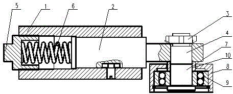
[0017] The invention discloses a rolling cutter head, which comprises a cutter shell 1, a cutter body 2 arranged in the cutter casing 1, one end of the cutter body 2 extends out of the cutter casing 1, and a rolling cutter head 4 is fixed at the port by a fastening bolt 3, and the other An adjusting bolt 5 is arranged at one end, and a spring 6 is arranged between the adjusting bolt 5 and the knife body 2 .

[0018] Wherein, the rolling cutter head 4 includes a mandrel 7, the upper end of the mandrel 7 is connected to the blade body 2 through a fastening bolt 5, and a roller 8 is provided at the lower end, and a self-aligning bearing is also provided between the mandrel 7 and the roller 8 9. The outer side of the mandrel 7 is covered with a transition sleeve 10; when the roller used by the self-aligning bearing is in use, it can automatically adjust according to the su...


PUM


Abstract

The invention discloses a rolling cutter bit, comprising a cutter shell and a cutter body; the cutter body is arranged in the cutter shell; one end of the cutter body extends out of the cutter shell; the rolling cutter bit is fixed by the end port of the cutter body by a fastening bolt; the other end of the cutter body is provided with a regulating bolt; a spring is arranged between regulating bolt and the cutter body. The rolling cutter bit disclosed by the invention is simple in structure and capable of effectively overcoming cutter aligning errors and inconsistent workpiece surface hardness, and the machining precision is improved.

Description

technical field [0001] The invention relates to a machining accessory, in particular to a rolling cutter head. Background technique [0002] Nowadays, the competition in the parts processing industry is quite fierce. How to improve the processing quality, improve the processing level, and save processing costs has become an urgent matter. [0003] After reviewing the relevant information, the required roughness can be achieved by using turning, boring, drawing, grinding, end milling, scraping, rolling and other processing methods. However, combined with the existing processing equipment and the characteristics of the parts themselves, the The main shaft can only be processed on CNC vertical lathe, so it can only be selected between lathe and rolling; for Siemens and Ruineng bearing housings, it can only be bored on a CNC boring machine. [0004] Rolling processing is a kind of plastic processing method that rolls a high-hardness and smooth roller into contact with a metal s...

Claims


Application Information

Patent Timeline
Patent Type & Authority Applications(China)
IPC IPC(8): B23P9/02
CPCB23P9/02
Inventor 于灿其
Owner NANJING HAOWEI MACHINERY
Why Eureka
Try Eureka