Feeding device, machine tool adopting feeding device and machining method thereof

A technology of feeding device and moving device, applied in the direction of driving device, feeding device, metal processing equipment, etc., can solve problems such as reducing processing efficiency, and achieve the effect of improving processing efficiency

Active Publication Date: 2014-10-15
富联科技(山西)有限公司
View PDF5 Cites 1 Cited by
  • Summary
  • Abstract
  • Description
  • Claims
  • Application Information

AI Technical Summary

Problems solved by technology

In this way, the proc...

Method used


Image

  • Feeding device, machine tool adopting feeding device and machining method thereof
  • Feeding device, machine tool adopting feeding device and machining method thereof
  • Feeding device, machine tool adopting feeding device and machining method thereof

Examples


Embodiment Construction

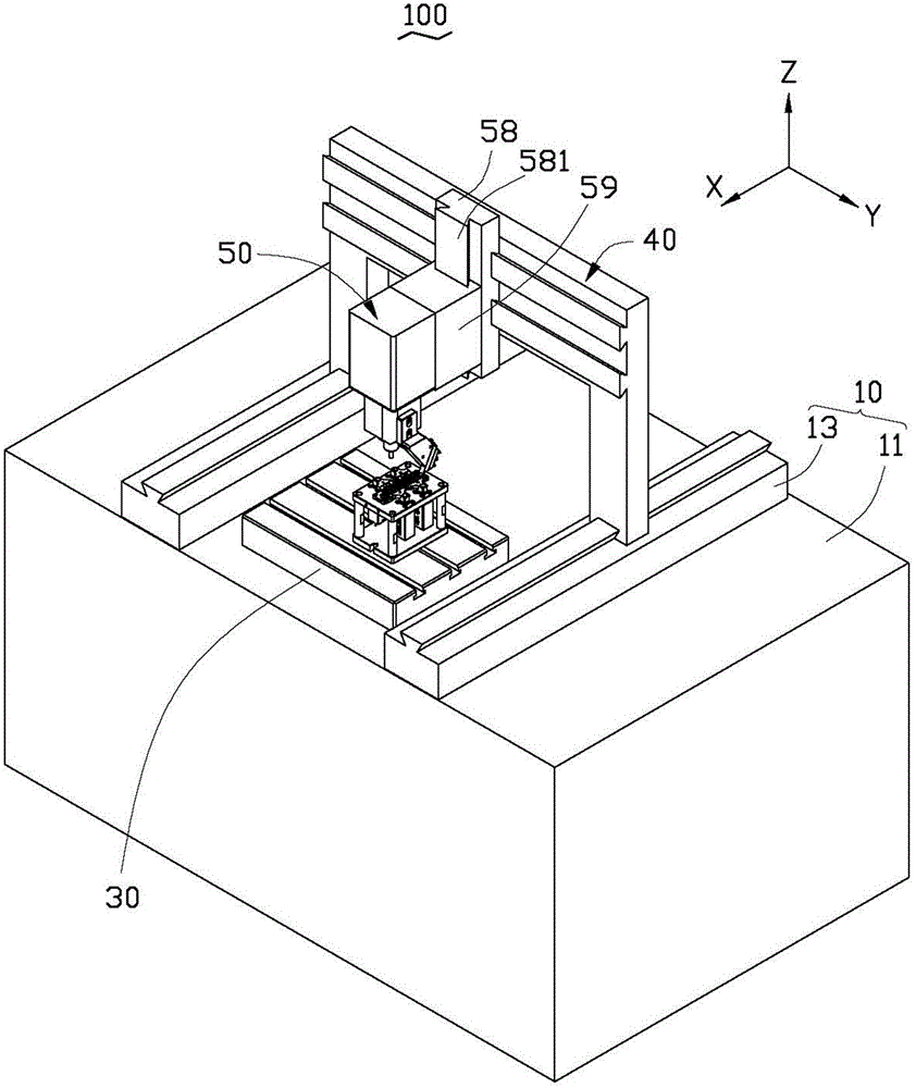
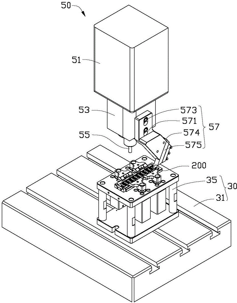
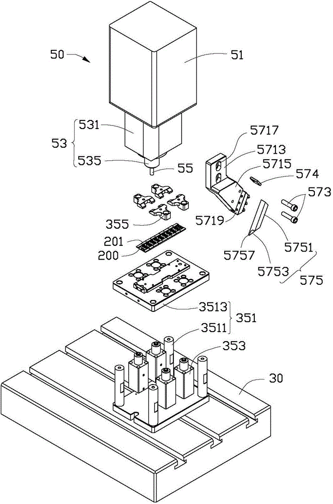
[0020] see figure 1 and figure 2 , the machine tool 100 according to the first embodiment of the present invention is used to perform combined milling and planing processing on a workpiece 200 . The machine tool 100 includes a machine table 10 , a table 30 , a moving device 40 and a feeding device 50 . The workbench 30 is arranged on the machine platform 10, the mobile device 40 is movably installed on the machine platform 10 along the first direction X, and the feeding device 50 is installed on the mobile device 40 and can move relative to the mobile device 40 along the second direction Y and slide in the third direction Z. Certainly, the machine tool 100 also includes other structures such as a controller, such as a driving device for driving the moving device 40 to move. In this embodiment, in order to save space, the description of other structures is omitted, and the omitted part does not affect the technical solution of the present invention.

[0021] Please combine...


PUM


Abstract

The invention provides a feeding device. The feeding device comprises a connection seat, a main shaft arranged on the connection seat and a milling cutter, wherein the main shaft comprises a fixed part and a rotary part which is in rotary connection with the fixed part; the fixed part is connected with the connection seat; the milling cutter is fixedly connected with the rotary part. The feeding device is characterized by further comprising a plane cutter assembly arranged on the fixed part; the plane cutter assembly comprises a tool rest and a plane cutter which is fixedly arranged on the tool rest; the tool rest comprises a connection part and a mounting part which is formed by extending from one end of the connection part in a certain angle; the connection part is fixedly connected with the fixed part; the plane cutter is arranged at one end, which is far away from the connection part, of the mounting part; the plane cutter extends in a direction far away from the connection part, and a certain angle is formed between the plane cutter and the mounting part; a profiled cutting edge is arranged at one end, which is far away from the tool rest, of the plane cutter. The invention further provides a machine tool adopting the feeding device and a machining method thereof.

Description

technical field [0001] The invention relates to a feeding device, in particular to a milling and planing compound feeding device, a milling and planing compound machine tool using the milling and planing compound feeding device and a processing method thereof. Background technique [0002] In industry, the feed device often includes a main shaft and a milling cutter mounted on the main shaft. In order to process the surface of some workpiece or a certain part of the surface into a curved surface with an external R angle, it is usually used to mill the two sides of the workpiece, that is, the spindle drives the milling cutter to mill along the edge of one side of the workpiece, and then to the other opposite side. The side edge is milled back and forth twice to form a connected curved surface. The curved surface processed by the feeding device can easily form a bonding line mark at the junction of the curved surfaces. In order to eliminate the joint line marks, subsequent t...

Claims


Application Information

Patent Timeline
IPC IPC(8): B23P23/02B23Q5/04
CPCB23P23/02B23Q5/22B23D11/00B23Q1/25Y10T409/303752Y10T409/30784
Inventor 王雪松庄德计
Owner 富联科技(山西)有限公司
Why Eureka
Try Eureka