
Distributor for lifting large thin-wall safety shell and passive water tank and force transfer method thereof

A containment and passive technology, which is applied in the direction of transportation and packaging, load suspension components, etc., can solve the problems of not taking into account the large bending moment, the transition beam cannot be arranged reasonably, and the integrity of the distributor is poor, so as to reduce the shear Stress, avoiding cracking at weld joints, and strong integrity

Active Publication Date: 2014-10-15
ZHEJIANG UNIV +1
View PDF6 Cites 13 Cited by
  • Summary
  • Abstract
  • Description
  • Claims
  • Application Information

AI Technical Summary

Problems solved by technology

However, the containment bottom head used in CAP1400 nuclear power technology has a total of 18 lifting points. If the distributor is also designed using the transition beam as the main structure, there will be a problem that the position of the transition beam cannot be properly arranged.
[0005] In addition, the design of the CV hoisting distributor of AP1000 nuclear power plant only considers the transmission of oblique tension, and does not take into account the large bending moment caused by the distance between the lug plate and the center of the distributor, and the integrity of the distributor is poor. It is easy to have safety accidents during use

Method used


Image

  • Distributor for lifting large thin-wall safety shell and passive water tank and force transfer method thereof
  • Distributor for lifting large thin-wall safety shell and passive water tank and force transfer method thereof
  • Distributor for lifting large thin-wall safety shell and passive water tank and force transfer method thereof

Examples


Embodiment Construction

[0026] In order to make the present invention more comprehensible, specific embodiments are described below in detail with accompanying drawings.

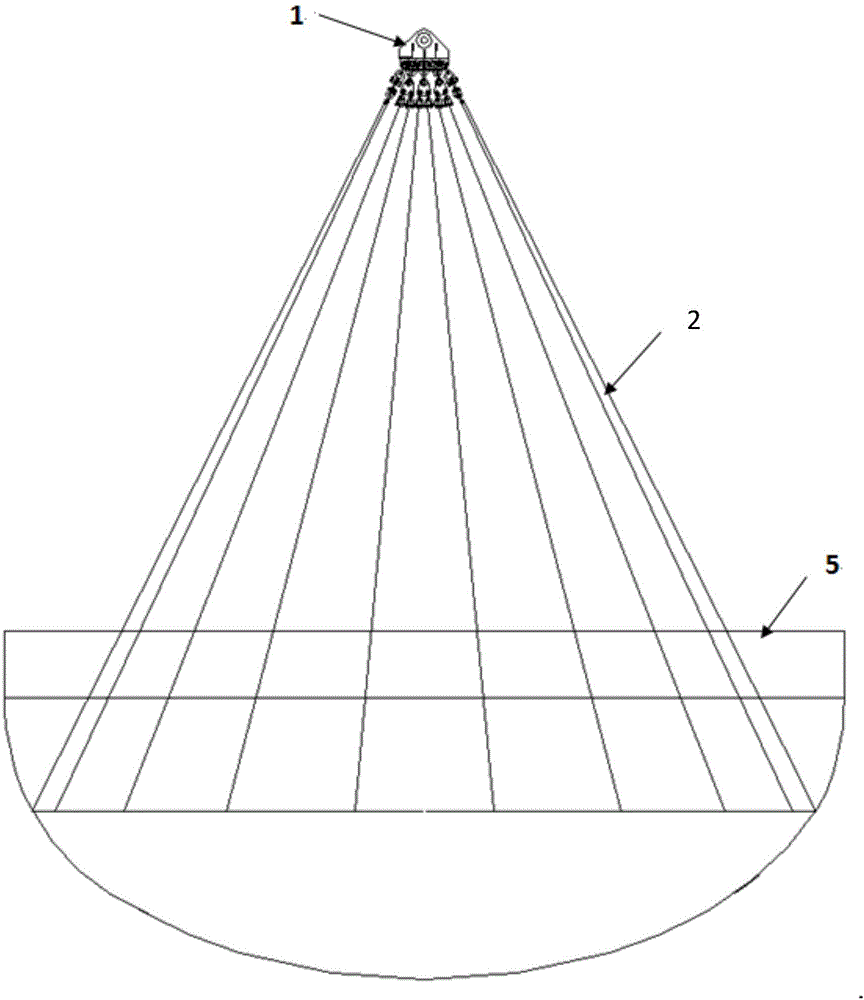
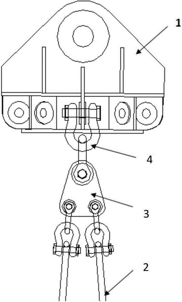
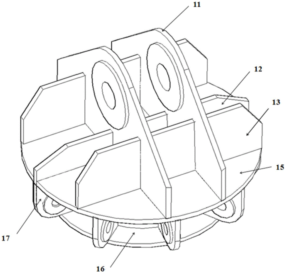
[0027] Such as image 3 As shown, the present invention provides a distributor for the hoisting of CAP1400 containment and cooling water tanks, and uses the triangular plate and the shackle connection to realize the equidistant arrangement of the slings, so that the stress on each sling is even and does not interfere with each other, ensuring safety There is no large deformation of the shell bottom head during hoisting. The present invention includes two first lifting bases 11, a second lifting base 12, two reinforcements 13, an annular support beam 14, a connecting plate 15, a bottom plate 16, and nine lug plates 17. Block triangle plate 3, shackle 4.

[0028] The two first lifting bases 11 are connected to the upper hanger through pin shafts, the second lifting base 12 is welded on the two first lifting bases 11, and two reinfo...


PUM


Abstract

The invention discloses a distributor for lifting a large thin-wall safety shell and a passive water tank and a force transfer method thereof. The distributor comprises two first lifting bases, a second lifting base, two reinforcement pieces, an annular support beam, a connecting plate, a baseplate and nine lifting lug plates, wherein the second lifting base is welded on the two first lifting bases; the two reinforcement pieces are arranged at the two sides of the second lifting base, and are symmetrically welded on the two first lifting bases; the bottoms of the two reinforcement pieces are welded with the connecting plate; the annular support beam is welded at the lower parts of the first lifting bases and the second lifting base; the bottoms of the annular support beam, the first lifting bases and the second lifting base are leveled with each other; the annular support beam, the first lifting bases and the second lifting base are all welded on the baseplate; the lifting lug plates are welded in an annular groove, consisting of the annular support beam, the connecting plate and the baseplate, at intervals; and each of the lifting lug plates is connected with a triangular plate through a pair of shackles. The distributor has good structural integrity; and a whole system consisting of the baseplate, the annular support beam and the connecting plate can bear bending moment generated by the lifting lug plates deviating from the center position of the distributor.

Description

technical field [0001] The invention belongs to the technical field of hoisting, and relates to a distributor used for hoisting a large thin-walled containment vessel and a cooling water tank and a force transmission method thereof. Background technique [0002] The steel containment vessel (CV) is one of the inner shielding structural components of the CAP1400 nuclear power plant reactor building, and the cooling water tank (CB20) is an important part of the passive containment cooling system, both of which are the core equipment of the third-generation nuclear power plant. It has the characteristics of large volume, large mass, and thin wall thickness. Therefore, it is easy to deform if the force is uneven or the design of the hoisting system is unreasonable during the hoisting process. [0003] Taking the steel containment bottom head component as an example, the CV components are usually hoisted by the following method: multiple steel wire ropes and adjustable pull rods ...

Claims


Application Information

Patent Timeline
IPC IPC(8): B66C1/12
Inventor 龚顺风厉沛程建棠程鹏楼军
Owner ZHEJIANG UNIV
Learn More