Sealing device for gas isolation of furnace sections

A sealing device and atmosphere technology, applied in heat treatment equipment, heat treatment process control, manufacturing tools, etc., can solve the problems of small sealing gas area, easy loosening, poor sealing performance, etc., to achieve convenient disassembly and installation, simple manufacturing and processing, and extended use The effect of longevity

Active Publication Date: 2014-10-15
WISDRI WUHAN WIS IND FURNACE
View PDF3 Cites 2 Cited by
  • Summary
  • Abstract
  • Description
  • Claims
  • Application Information

AI Technical Summary

Problems solved by technology

The current baffle has a solid structure and a small thickness (it is only composed of two steel plates sandwiching a layer of ceramic fiber cotton), which can only form a linear seal with the roller, so that the area for sealing the gas is small and the sealing effect is not good; the thickness is relatively large It consists of a number of fiber modules connected. Due to the large size of the fiber modules and the simple way of fixing each other, they are easy to loosen during use, and need to be replaced after the furnace is shut down once.
The sealing surface formed between the baffle and the rollers of this structure is small, and the sealing performance between the end of the baffle and the outside is poor, so the effect of isolating the atmosphere of the front and rear furnace sections is poor.

Method used


Image

  • Sealing device for gas isolation of furnace sections
  • Sealing device for gas isolation of furnace sections
  • Sealing device for gas isolation of furnace sections

Examples


Embodiment Construction

[0026] In order to better understand the present invention, the technical solutions of the present invention will be further described below in conjunction with the embodiments and the accompanying drawings.

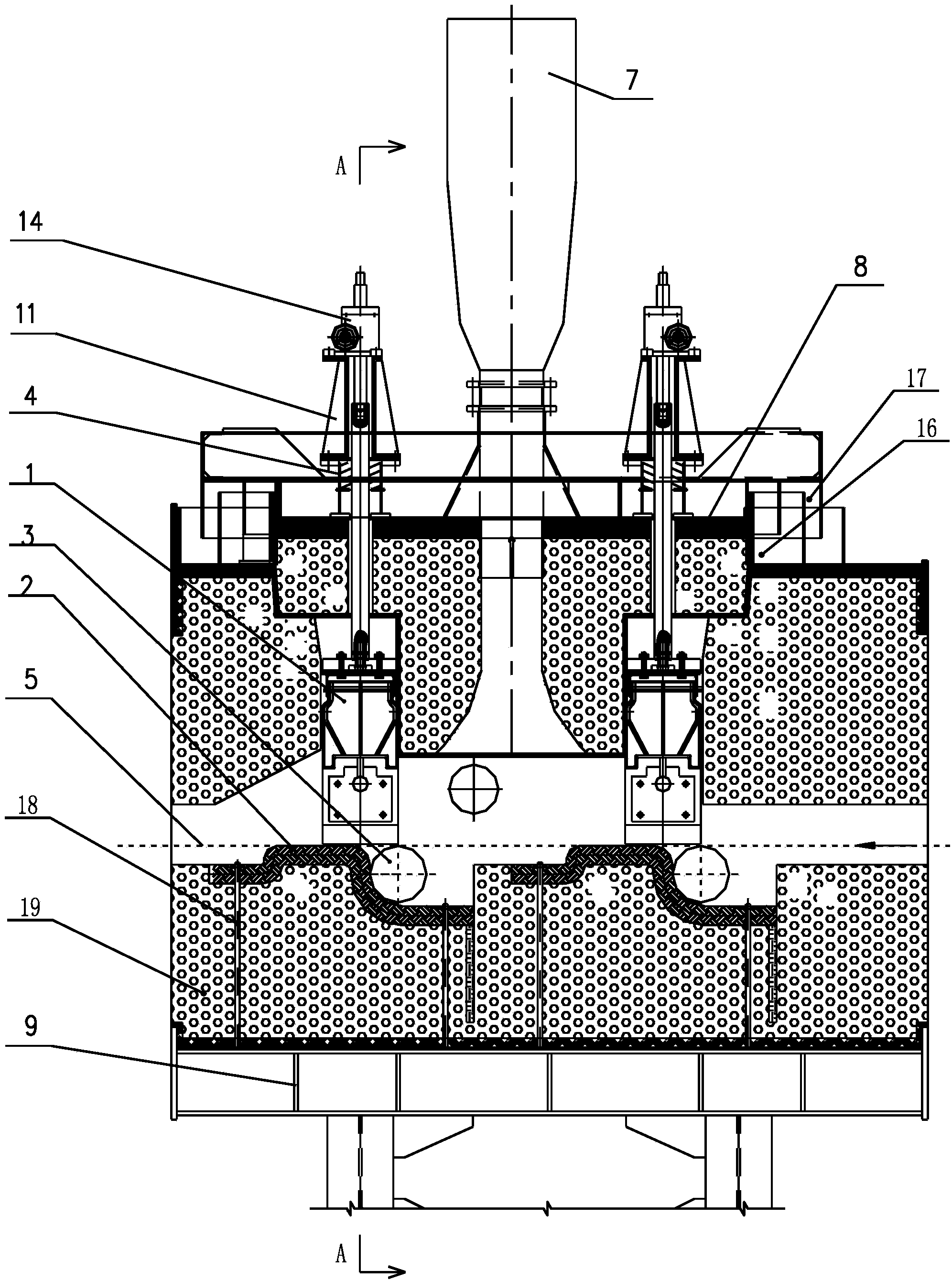
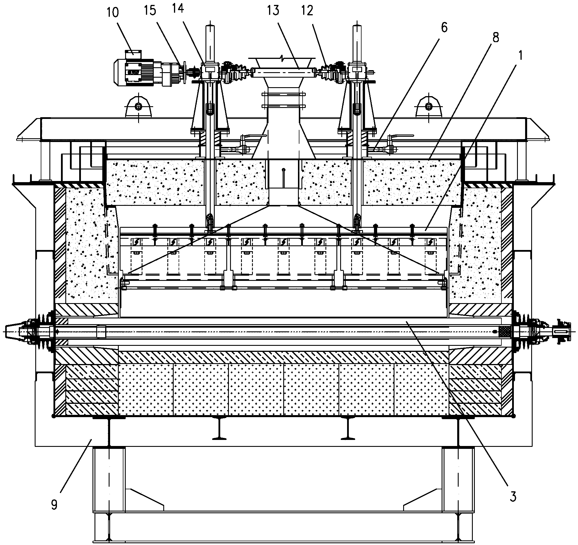
[0027] A sealing device for the atmosphere isolation of the furnace section (the device is arranged between the dry atmosphere and the wet atmosphere furnace section or between the heating section and the cooling section), which is mainly composed of a furnace shell steel structure 9 and a seal cover on the furnace shell steel structure 9 Furnace roof cover 8, refractory castables 19 are provided around the inside of the furnace shell steel structure 9, and a channel for the strip steel 5 to pass is provided in the middle. The passing line coincides; the lower surface of the furnace roof 8 is provided with an inverted "convex" shaped refractory castable 19, and a release channel 7 is provided in the middle of it (the gas flow between the two baffles is controlled by the r...


PUM


Abstract

The invention belongs to the field of sealing equipment for gas isolation of furnace sections in silicon steel heat processing technology, and particularly to a sealing device for gas isolation of furnace sections, especially for gas isolation of furnace sections of a high grade oriented silicon steel continuous annealing furnace. The sealing device for gas isolation of furnace sections comprises a furnace shell steel structure and a furnace top cover covered on the furnace shell steel structure in a sealing manner, wherein refractory cast materials are internally arranged around the furnace shell steel structure; a passage allowing a steel strip to penetrate through is arranged at the middle of the furnace shell steel structure; a pair of rollers are arranged in the passage; the upper surfaces of the rollers are overlapped with the steel strip through a line; T-shaped refractory cast materials are arranged on the lower surface of the furnace top cover; a diffusing passage is arranged at the middle of the furnace top cover; two baffles are arranged on the two sides of the diffusing passage; lifting devices are arranged at the upper ends of the baffles and mounted on the upper surface of the furnace top cover. According to the sealing device, gas flow in a front furnace section and a rear furnace section can be effectively controlled, the required furnace pressure can be precisely controlled, and the required isolating effect can be achieved.

Description

technical field [0001] The invention belongs to the field of sealing equipment for furnace section atmosphere isolation in the heat treatment process of silicon steel, in particular to a furnace section atmosphere isolation sealing device, especially for furnace section atmosphere isolation of high-grade and oriented silicon steel continuous annealing furnaces. Background technique [0002] According to the silicon steel heat treatment process, the dry atmosphere and wet atmosphere furnace section, the heating section and the cooling section all need to be separated from the atmosphere, and the atmosphere separation is realized by adjusting the furnace pressure, so a sealing device for furnace pressure control is required. At present, the equipment (that is, the sealing device) used for the atmosphere barrier of the furnace section on the silicon steel line is linearly sealed by baffles and rollers, and the top of the furnace is equipped with a release pipe to control the flo...

Claims


Application Information

Patent Timeline
Patent Type & Authority Applications(China)
IPC IPC(8): C21D1/26C21D11/00C21D1/74C21D6/00
Inventor 宋晓娜吴尚姚文方姚嵩
Owner WISDRI WUHAN WIS IND FURNACE
Why Eureka
Try Eureka