
Generator rotor winding temperature online monitoring method

A technology for generator rotors and rotor windings, applied to thermometers, thermometers using directly heat-sensitive electric/magnetic elements, measuring devices, etc., can solve the problems of generator dust, oil, water mist, complex tests, and short response times Slow down and other problems, to achieve the effect of improving monitoring work efficiency, accurate measurement accuracy, and eliminating voltage drop

Inactive Publication Date: 2014-10-15
贵阳新光电气有限公司
View PDF3 Cites 2 Cited by
  • Summary
  • Abstract
  • Description
  • Claims
  • Application Information

AI Technical Summary

Problems solved by technology

[0003] The first type is to pre-embed the temperature measuring element on the rotor winding, and measure the temperature of the rotor winding through a slip ring or a wireless transmission-reception method. The measurement accuracy is high, but because some parts rotate with the rotor, it is difficult to realize
The second type is to use infrared non-contact temperature measurement, but the infrared probe lens is easily affected by dust, oil, and water mist inside the generator, the effect is poor, the response time is also slow, and the application is less
This method is even more flawed: even if the influence of the temperature of the external circuit and carbon brushes is not considered, the voltage changes with the change of the rotor winding current
[0007] There are also literatures that use a fixed temperature value to subtract the temperature influence brought by the carbon brush resistance and its contact resistance with the slip ring, which lacks basis and also has defects.
[0008] (2) Some documents require that the rotor winding resistance-temperature test be carried out in the stop state and the no-load state respectively in order to obtain the resistance-temperature linear curve of the rotor winding. The test is complicated and inconvenient, especially in the no-load state The test requires a large external DC power source

Method used


Image

  • Generator rotor winding temperature online monitoring method
  • Generator rotor winding temperature online monitoring method
  • Generator rotor winding temperature online monitoring method

Examples


Embodiment 1

[0032] Embodiment 1, according to the generator excitation system parameter table provided by the generator manufacturer, a certain temperature T can be directly obtained C The corresponding rotor winding resistance R C , and then according to the definition of the resistance-temperature coefficient α of the rotor winding copper bar material, the formula T can be obtained L =(R L -R C ) / (α×R 0 )+T C , so as to calculate the real-time temperature T of the rotor winding 2 L . Among them, α is a constant 0.00393, R 0 is the temperature T provided by the manufacturer C The corresponding rotor winding resistance R C Converted to the resistance value of the rotor winding at 0°C, R 0 = R C / (1+α×T C ).

Embodiment 2

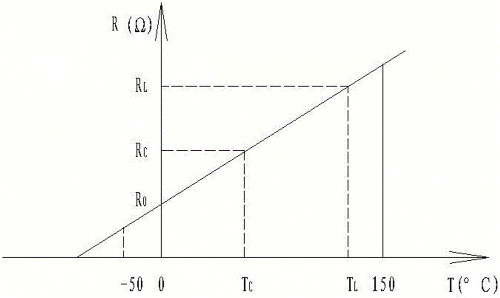
[0033] Embodiment 2, according to the definition of the resistance-temperature coefficient α of the copper bar material of the rotor winding, and the resistance-temperature curve of the copper bar material of the rotor winding ( image 3 ), you can get the formula T L =T C ×(R L -R 0 ) / (R C -R 0 ), so as to calculate the real-time temperature T of the rotor winding 2 L . Among them, R 0 is the temperature T provided by the manufacturer C The corresponding rotor winding resistance R C Converted to the resistance value of the rotor winding at 0°C, R 0 = R C / (1+α×T C ), α is a constant 0.00393. When given R C itself is T C When is the resistance value at 0°C, the real-time temperature T of the rotor winding L =(R L / R C -1) / α.

Embodiment 3

[0034] Embodiment 3, according to the resistance-temperature curve ( Figure 4 ), you can get the formula T L =(T C +235)×R L / R C -235, so as to calculate the real-time temperature T of the rotor winding 2 L .

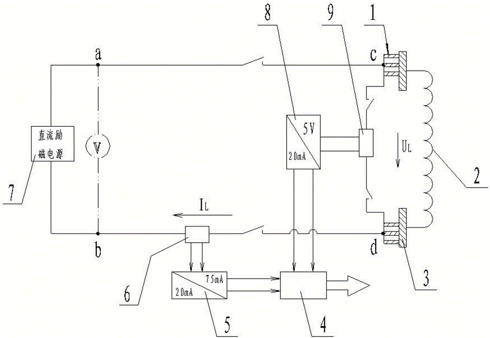
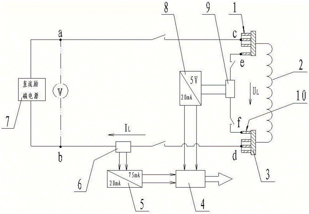
[0035] In order to further eliminate the influence of the resistance of the carbon brush group 1 and the contact resistance between the carbon brush group 1 and the slip ring 3 on the monitoring temperature, on the basis of the above-mentioned embodiments, it is also possible to use figure 2 The connection method directly collects the DC voltage U between the two slip rings L . That is: the DC excitation power supply 7 is connected to the two carbon brush groups 1 respectively fixed on the two slip rings 3 to form a circuit, and an auxiliary carbon brush 10 electrically isolated from the corresponding carbon brush group 1 is added to each of the two slip rings 3 as a voltage Monitoring point: collect the DC voltage U between the two carbon brush groups 1 in re...


PUM


Abstract

The invention discloses a generator rotor winding temperature online monitoring method capable of monitoring generator rotor winding temperature online. The method includes the steps of collecting voltage UL and current IL of a rotor winding in real time to obtain resistance RL of the rotor winding during operation of a generator; then converting the resistance into a temperature value TL of the rotor winding during operation of the generator according to the resistance-temperature relation of the rotor winding. By means of the method, the effects of external loop resistance, carbon brush resistance and contact resistance of the rotor winding on the resistance and temperature of the rotor winding are removed. The method has the advantages of being accurate and convenient to monitor, high in efficiency, free of onsite testing and capable of monitoring the generator rotor winding temperature online.

Description

technical field [0001] The invention relates to a method for on-line monitoring of generator temperature, in particular to a method for on-line monitoring of generator rotor winding temperature. Background technique [0002] The temperature of the generator rotor winding is very important to the safe and stable operation of the generator. At present, there are roughly three types of methods for online monitoring of generator rotor winding temperature: [0003] The first type is to pre-embed the temperature measuring element on the rotor winding, and measure the temperature of the rotor winding through a slip ring or a wireless transmission-reception method. The measurement accuracy is high, but it is difficult to realize because some parts rotate with the rotor. The second type is to use infrared non-contact temperature measurement, but the infrared probe lens is easily affected by dust, oil, and water mist inside the generator, the effect is poor, the response time is slow...

Claims


Application Information

Patent Timeline
IPC IPC(8): G01K7/16
Inventor 曾广
Owner 贵阳新光电气有限公司
Learn More