
Optical module and optical transceiver module

A technology of optical modules and optical components, applied in the coupling of optical waveguides, etc., can solve the problems of high overall production cost, inability to miniaturize the volume of laser diode modules, and light loss.

Inactive Publication Date: 2016-08-10
DELTA ELECTRONICS INC
View PDF4 Cites 0 Cited by
  • Summary
  • Abstract
  • Description
  • Claims
  • Application Information

AI Technical Summary

Problems solved by technology

[0003] Existing optical fiber communication mainly uses laser diodes packaged in a transistor-shaped can (TO-can) as the light-emitting terminal. However, laser diodes packaged in a transistor-shaped can can only be installed vertically on the circuit board. Difficulty increasing to the optical fiber, and causing some light to be lost during coupling
[0004] In addition, transistor-shaped cans are mostly made of metal materials, and the overall manufacturing cost is high, which makes the laser diode module packaging volume unable to be miniaturized

Method used


Image

  • Optical module and optical transceiver module
  • Optical module and optical transceiver module
  • Optical module and optical transceiver module

Examples


Embodiment Construction

[0044] The above and additional objects, features and advantages of the present invention will be better understood through the following illustrative and non-limiting detailed description of preferred embodiments of the present invention with reference to the accompanying drawings.

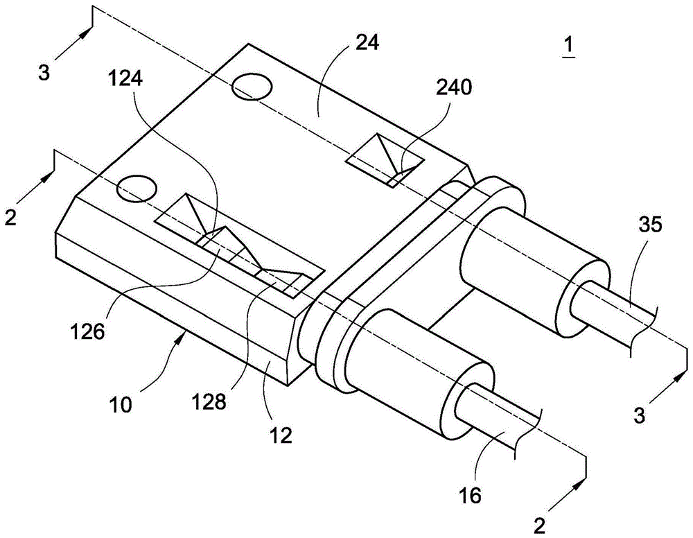
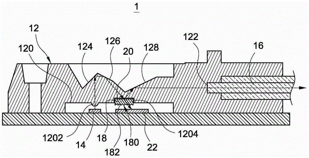
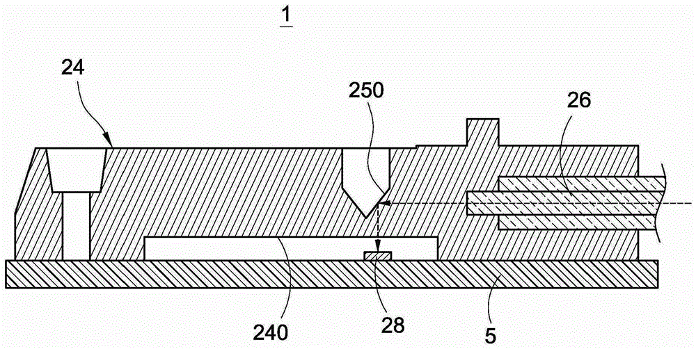
[0045] Cooperate with reference figure 1 and figure 2 , figure 1 is a perspective view of the optical transceiver module of the present invention, figure 2 for along figure 1 Sectional view of line 2-2. The optical transceiver module 1 includes an optical module 10 , and the optical module 10 includes a first light guiding element 12 , an optical element 14 , a first optical fiber 16 and a light splitting element 18 .

[0046] The refractive index of the first light guide element 12 is preferably between 1.12 and 2.08. The first light guide element 12 includes a first surface 120 and a second surface 122, the first surface 120 and the second surface 122 are preferably facing a first direct...


PUM


Abstract

The invention discloses an optical module and an optical transceiver module. The optical module includes a first light guiding element, an optical element, a first optical fiber, and a light splitting element. The first light guiding element includes a first surface and A second surface, the optical element is located on the first surface, the first optical fiber is in contact with the second surface, the light splitting element is attached to the first surface, and is used for partial reflection and partial transmission of light transmitted to the light splitting element For light beams, the refractive index of the light splitting element is different from the refractive index of the first light guiding element. The invention can solve the technical problem that the difficulty of coupling light to the optical fiber in the prior art is increased, and part of the light is lost during coupling.

Description

technical field [0001] The invention relates to an optical module and an optical transceiver module, in particular to an optical module and an optical transceiver module which use total internal reflection to change the transmission path of light beams. Background technique [0002] Optical fiber communication refers to a way of transmitting information by using light and optical fiber. It belongs to a kind of wired communication, which has the advantages of large transmission capacity and good confidentiality, and has gradually become the most important wired communication method today. [0003] Existing optical fiber communication mainly uses laser diodes packaged in a transistor-shaped can (TO-can) as the light-emitting terminal. However, laser diodes packaged in a transistor-shaped can can only be installed vertically on the circuit board. Difficulty in getting to the fiber increases, and some light is lost during coupling. [0004] In addition, the transistor-shaped c...

Claims


Application Information

Patent Timeline
Patent Type & Authority Patents(China)
IPC IPC(8): G02B6/42
Inventor 廖育贤黄铭益杨德炫
Owner DELTA ELECTRONICS INC
Learn More