Miniature Electric Wave Meter Signal Emission Device

A technology of signal transmission and radio wave watch, which is applied to electrical components, radio-controlled timers, transmission systems, etc., and can solve problems such as greatly discounted and unstable reception of radio wave signals

Inactive Publication Date: 2014-10-15
吴国忠
View PDF5 Cites 3 Cited by
  • Summary
  • Abstract
  • Description
  • Claims
  • Application Information

AI Technical Summary

Problems solved by technology

Since the positions of the radio wave base stations of the above-mentioned six bureaus in the world are different, and the signal sent by the radio wave sending base station of the radio-controlled watch has a limit of 1000-1500 kilometers, when the consumer, if the signal of the Japanese or Chinese base station is not set, then the consumer in Taiwan Radio-controlled watches are useless
In addition, radio-controlled watches are used in China. Although there are three base stations in China and Japan that can receive radio waves, the distance between Taiwan, China and the two base stations in China or Japan exceeds the limit of 1,000 kilometers for better signals. The reception is not very stable, and it is often necessary to be in an open area in the middle of the night to successfully receive the radio wave sending base station. The correction time signal sent by the domestic watch industry and radio wave watch users can be said to be greatly reduced. Therefore, How to allow domestic consumers or general consumers to quickly receive the corrected time radio signal sent by the radio transmission base station at home or around the world is the main demand of the present invention

Method used


Image

  • Miniature Electric Wave Meter Signal Emission Device
  • Miniature Electric Wave Meter Signal Emission Device

Examples


Embodiment Construction

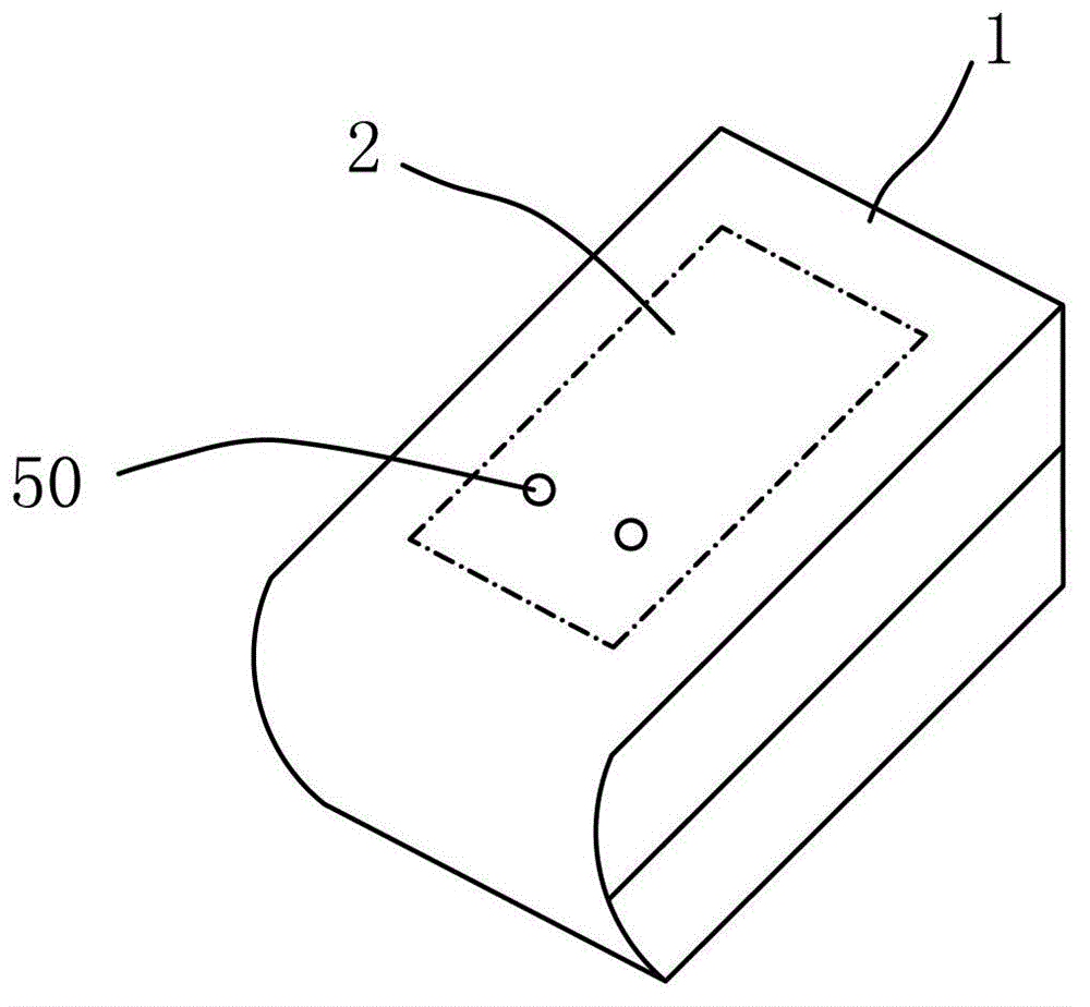
[0016] A kind of miniature radio-wave watch signal transmitting device of the present invention, such as figure 1 Shown includes a body 1, the body 1 is preferably a combination of two detachable shells, so that a signal processing unit 2 can be accommodated inside the body 1. In addition, the main body 1 may be provided with a display unit at an appropriate place according to actual needs, and the display unit may be a monochrome or colorful liquid crystal display screen, or may be light emitting elements (preferably light emitting diodes) of at least two colors, so as to This provides the user with identification that the main body is currently in the signal receiving state or the meter wave standard clock signal transmitting state.

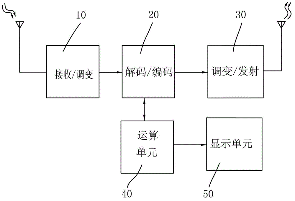
[0017] Please refer to figure 2 As shown, the signal processing unit 2 has a built-in signal receiving and modulating unit 10, a decoding and encoding unit 20, a computing unit 40, a modulating and transmitting unit 30, and a display unit 50:...


PUM


Abstract

The present invention discloses a miniature electric wave meter signal emission device. The miniature electric wave meter signal emission device is mainly characterized in that a signal processing unit is arranged in a body, and a signal receiving and modulation unit for specifically receiving a cesium iridium atomic clock signal in a global positioning system or a mobile phone communication system is arranged in the signal processing unit; the modulated clock signal is decoded by a coding and decoding unit, then is sent to an operation unit to calculate and accumulate the distance time difference from an emission signal to the signal processing unit, and then is transmitted back to the coding and decoding unit to recode, and finally is transmitted to a modulation and emission unit for modulation, so that the clock signal received by an electric wave meter is corrected to emit, and the users using the electric wave meter receive and correct the time difference.

Description

technical field [0001] The invention relates to the field of a signal transmitting device, in particular to a miniature radio wave watch transmitting device for power supply wave watch correction. Background technique [0002] The invention of clocks and watches allowed humans to have a more precise grasp of time, and with the development of technology, radio-controlled watches came out. [0003] The reason why radio-controlled watches are so popular among consumers is that an ultra-miniature antenna is installed at 12 o’clock inside the watch to receive the radio-wave sending base station of the radio-controlled watch and send the radio wave signal for correcting time, and the watch receives the radio wave for correcting time. After that, the time can be automatically analyzed and corrected, and the time can be adjusted by automatically receiving radio waves regularly without any error. The reason why the radio signal has no error is that the base station timepiece that se...

Claims


Application Information

Patent Timeline
IPC IPC(8): G04R20/14G04R20/16G04R20/18G04R20/02G04R20/04G04R20/06G04R40/00H04B1/02
Inventor 吴国忠
Owner 吴国忠
Why Eureka
Try Eureka