Eureka AIR delivers breakthrough ideas for toughest innovation challenges, trusted by R&D personnel around the world.

Integrated fuse

A fuse, an integrated technology, applied in the field of electrical safety protection devices, can solve the problems of improper production and assembly of melts and end caps, affecting the normal operation of the circuit, complex fuse structure, etc., achieving a simple structure and reducing the possibility of poor contact The effect of low performance, production cost and use cost

Inactive Publication Date: 2014-10-15
东莞市博钺电子有限公司
View PDF7 Cites 1 Cited by
  • Summary
  • Abstract
  • Description
  • Claims
  • Application Information

AI Technical Summary

Problems solved by technology

[0003] The current fuse, the fuse and the end cap are in a split structure, which on the one hand makes the structure of the fuse more complicated and the production cost is higher. On the other hand, the melt and end cap in a split structure are prone to improper production and assembly. Poor contact will affect the normal operation of the circuit

Method used


Image

  • Integrated fuse
  • Integrated fuse
  • Integrated fuse

Examples


Embodiment Construction

[0022] In order to describe the technical content, structural features, achieved goals and effects of the present invention in detail, the following will be described in detail in conjunction with the embodiments and accompanying drawings.

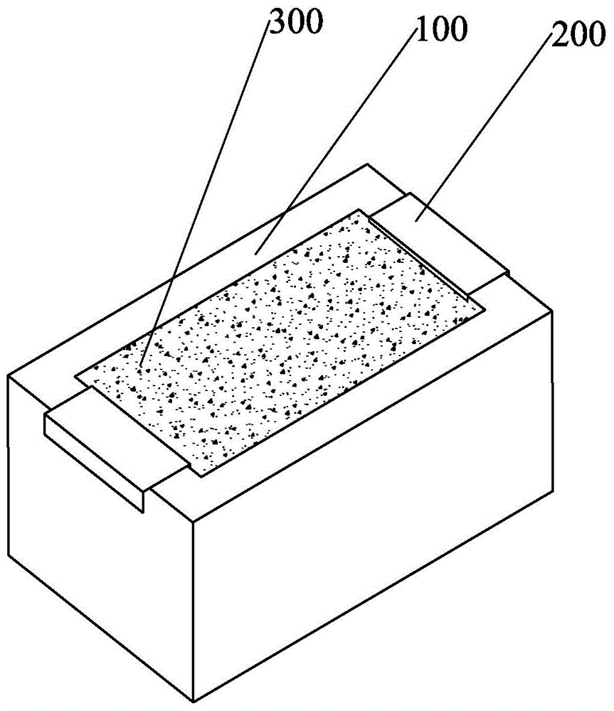
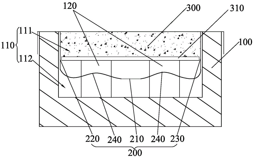
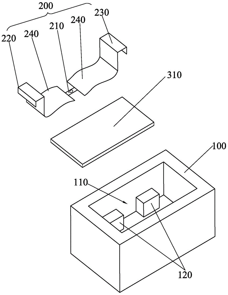
[0023] Figure 1-Figure 4 Shown is a schematic diagram of the first embodiment of the integrated fuse of the present invention.

[0024] Such as figure 1 and figure 2 The one-piece fuse shown includes an insulating case 100 , a fuse 200 and a shielding layer 300 . One side of the insulating housing 100 is recessed inwardly to form an accommodating cavity 110, so that the peripheral side of the accommodating cavity 110 is closed and only the upper part is open; the melt 200 includes a fuse part 210, a first conductive end 220 and a second conductive end 230, The fuse part 210 is disposed in the accommodating cavity 110, and the two ends of the fuse part 210 are respectively connected to the first conductive end 220 and the second conduc...


PUM


Abstract

The invention discloses an integrated fuse. The integrated fuse comprises an insulating shell and a fusant, wherein one side of the insulating shell is sunk inwards to form a containing cavity; the fusant comprises a fusing part, a first conductive end and a second conductive end; the fusing part is arranged in the containing cavity; the two ends of the fusing part are respectively connected with the first conductive end and the second conductive end; the first conductive end and the second conductive end stretch out of the containing cavity; the containing cavity is internally provided with a shielding layer for shielding the fusing part. According to the invention, the provided integrated fuse is simple in structure, steady in performance, relatively low in production cost and relatively low in use cost.

Description

technical field [0001] The invention relates to an electrical safety protection device, in particular to a fuse for short circuit and overload protection. Background technique [0002] A fuse usually includes a melt, an insulating tube covering the melt, and end caps fixedly connected to both ends of the insulating tube and electrically connected to the melt. The external circuit is capped at both ends to allow the current to flow through the melt. When the current flowing through the melt exceeds the specified value, the heat generated by the melt itself will cause the melt to fuse and disconnect the circuit, thereby protecting against short circuit and overcurrent. It is one of the most commonly used circuit protection devices. [0003] The current fuse, the fuse and the end cap are in a split structure, which on the one hand makes the structure of the fuse more complicated and the production cost is higher. On the other hand, the melt and end cap in a split structure are...

Claims


Application Information

Patent Timeline
Patent Type & Authority Applications(China)
IPC IPC(8): H01H85/05H01H85/143H01H85/36
Inventor 何旭斌赵志成郭晓冬
Owner 东莞市博钺电子有限公司
Why Eureka
Eureka Blog
Learn More