Wafer defect size correction method

A technology of defect size and correction method, which is applied in the direction of electrical components, semiconductor/solid-state device manufacturing, semiconductor/solid-state device testing/measurement, etc., can solve the problem of inability to obtain accurate defect size distribution, etc., to facilitate analysis and shorten a lot of time , the effect of improving accuracy

Active Publication Date: 2014-10-15
SHANGHAI HUALI INTEGRATED CIRCUTE MFG CO LTD
View PDF3 Cites 4 Cited by
  • Summary
  • Abstract
  • Description
  • Claims
  • Application Information

AI Technical Summary

Problems solved by technology

[0007] In order to achieve the purpose of the present invention, the present invention provides a wafer defect size correctio...

Method used


Image

  • Wafer defect size correction method
  • Wafer defect size correction method
  • Wafer defect size correction method

Examples


Embodiment Construction

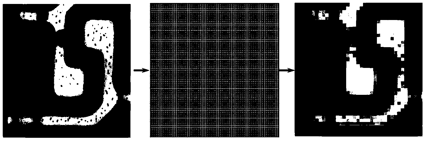
[0033] see Figure 4 , the wafer defect size correction method of the present embodiment includes the following steps:

[0034] Step S01, providing a wafer to be inspected;

[0035] Step S02, using the defect detection equipment to perform defect detection on the region to be detected on the wafer, and selecting a number of detected defects, and obtaining the first size of the selected defects, wherein the first size is determined by the defect detection Measured by equipment;

[0036] Step S03, using defect observation equipment to observe the defect morphology of the area to be inspected, and measure the second size of the selected defects, wherein the second size is obtained by measuring the defect observation equipment;

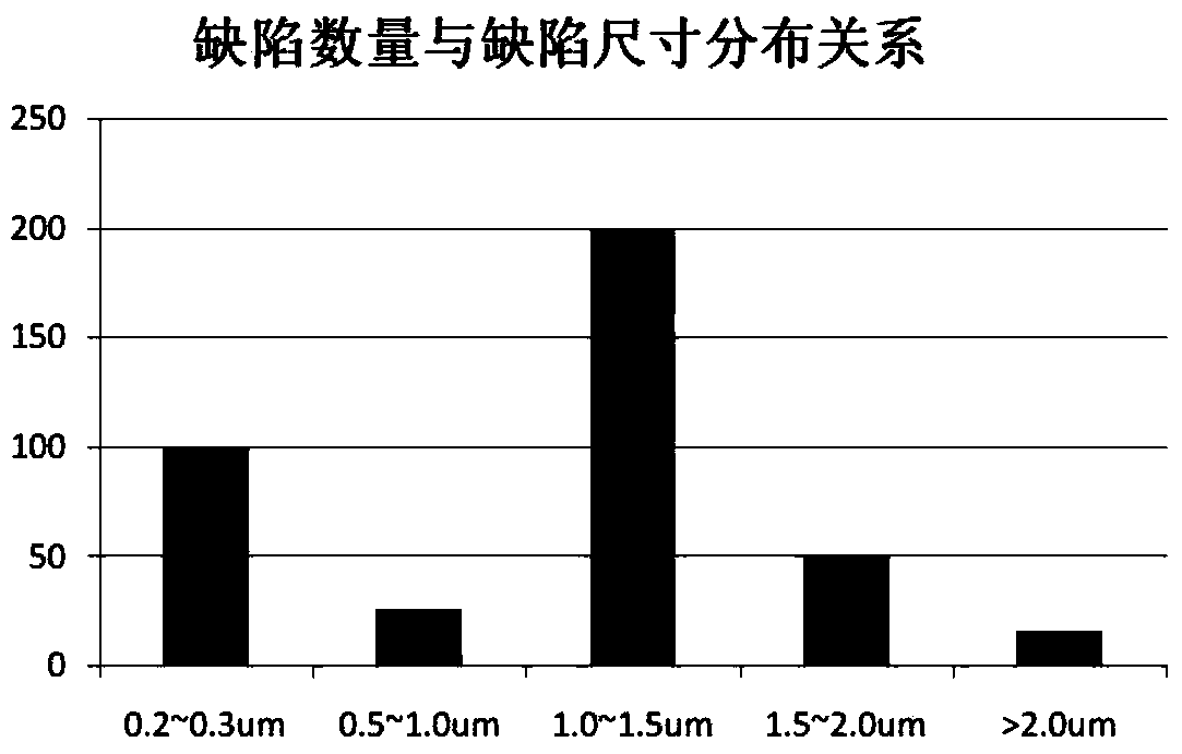
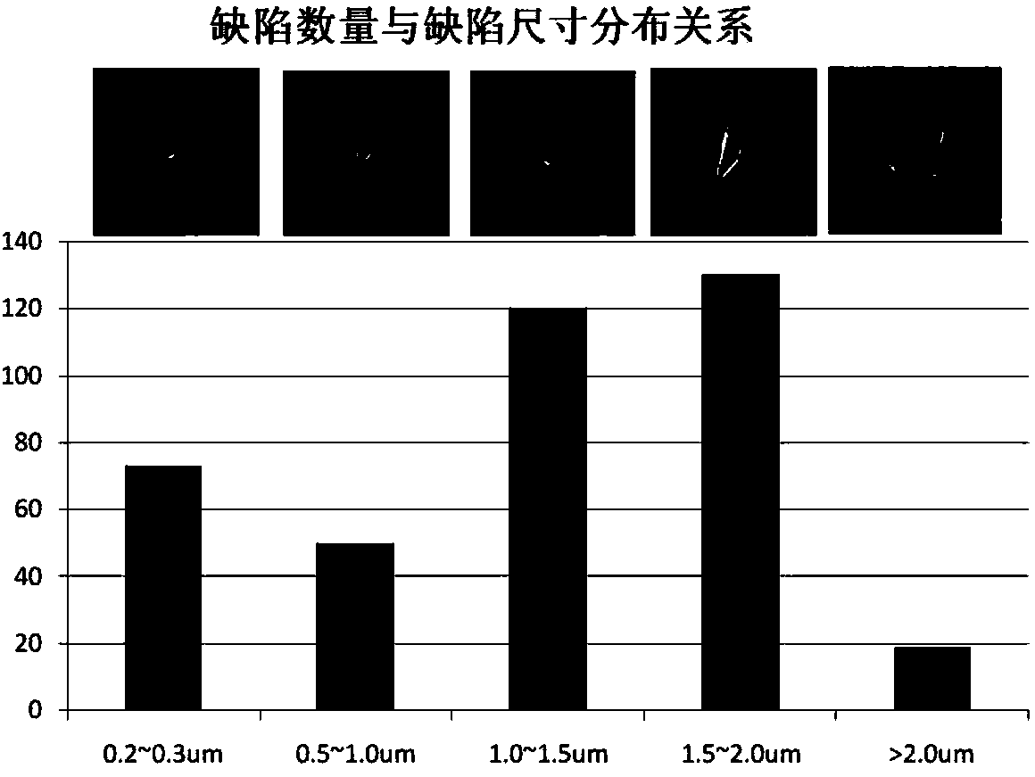
[0037] Step S04: Based on the second size, the correction value of the first size of the plurality of defects is obtained, wherein the first size of each defect in the plurality of defects is compared with the second size one by one, and the corrected v...


PUM


Abstract

The invention discloses a wafer defect size correction method. By using the advantage of accurate observation and measurement of defect sizes of defect observation equipment, linkage is established with defect detection equipment after the sizes of a plurality of selected defects are measured by using the defect observation equipment, a corresponding defect correction relation is established, and the defect size defining accuracy of the defect detection equipment is corrected automatically, thereby greatly increasing the accuracy of defect size distribution measured by using the defect detection equipment, shortening a large amount of time for measuring sizes through the defect observation equipment, and contributing to analysis of a large amount of engineering data. The defect size distribution on a wafer can be well grasped before performing defect shape analysis.

Description

technical field [0001] The invention relates to the technical field of semiconductor manufacturing, in particular to a method for correcting the defect size of a wafer. Background technique [0002] The manufacturing process of a chip often includes hundreds of steps. The main process modules can be divided into several major parts such as photolithography, etching, ion implantation, film growth and cleaning. In the actual production process, small errors in any link will All will lead to the failure of the final electrical performance of the entire chip. Especially as the critical dimensions of the circuit continue to shrink, the requirements for process control are becoming more and more stringent. Therefore, in order to detect and solve problems in time in the actual production process, it is necessary to be equipped with high-sensitivity optical and electron beam defects. The inspection equipment conducts on-line inspection of the product, and then uses electron microsc...

Claims


Application Information

Patent Timeline
IPC IPC(8): H01L21/66H01L21/68
CPCH01L22/12H01L22/20
Inventor 倪棋梁陈宏璘龙吟
Owner SHANGHAI HUALI INTEGRATED CIRCUTE MFG CO LTD
Why Eureka
Try Eureka