
Optical cable fiber series connection detection device and method

A detection device and fiber optic connector technology, which is applied in the field of optical communication, can solve the problems of low detection efficiency and achieve the effects of short time consumption, convenient use, and prevention of bending loss

Inactive Publication Date: 2014-10-15
STATE GRID SHANDONG ELECTRIC POWER +1
View PDF4 Cites 7 Cited by
  • Summary
  • Abstract
  • Description
  • Claims
  • Application Information

AI Technical Summary

Problems solved by technology

[0005] For this reason, the technical problem to be solved by the present invention is that the detection efficiency of the method used for the detection of optical fiber in the prior art is low, so a kind of detection device and method for serial connection of optical fiber that can improve the detection efficiency is proposed

Method used


Image

  • Optical cable fiber series connection detection device and method
  • Optical cable fiber series connection detection device and method
  • Optical cable fiber series connection detection device and method

Examples


Embodiment 1

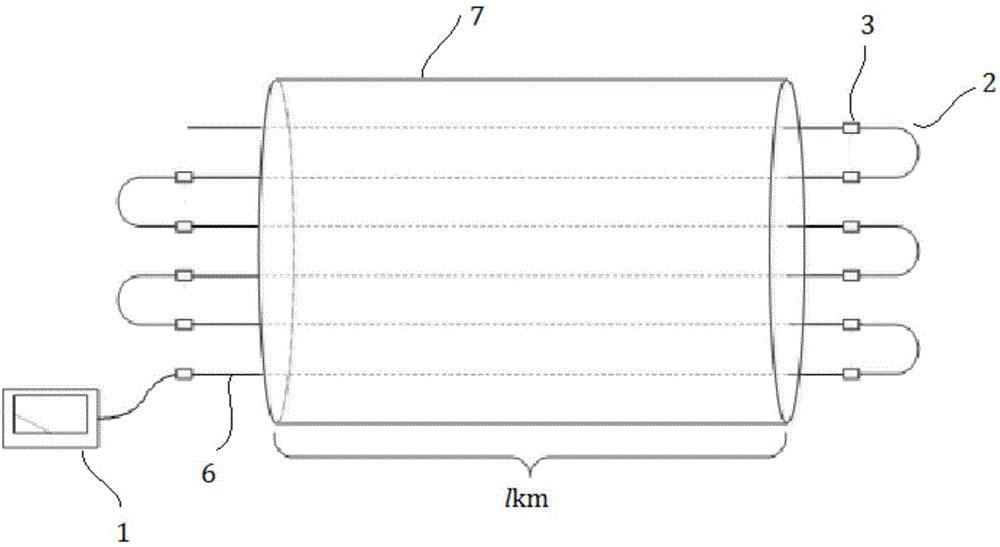
[0032] The present embodiment provides a kind of detection device of optical fiber serial connection of optical cable, such as figure 1 As shown, it includes an optical time domain reflectometer 1, at least two jumper fibers 2 and an optical fiber connector 3; the signal end of the optical time domain reflectometer 1 is connected to an end of an optical fiber 6 to be tested, and the The other end of the optical fiber 6 to be tested, the jumper fiber 2 and other optical fibers to be tested are connected end to end.

[0033] The optical fiber to be tested can be the entire optical fiber of the optical cable or multiple optical fibers on an optical cable. After the end-to-end connection of all optical fibers to be tested, a complete optical path can be formed. For the convenience of simplifying the illustration, Fig. Only draw a schematic diagram of the series connection of six optical fibers in one optical cable, two jumps are made at both ends of the optical cable 7, and the tw...

Embodiment 2

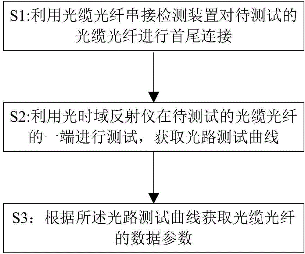
[0042] This embodiment provides a method for detecting the serial connection of optical fiber cables, such as image 3 shown, including the following steps:

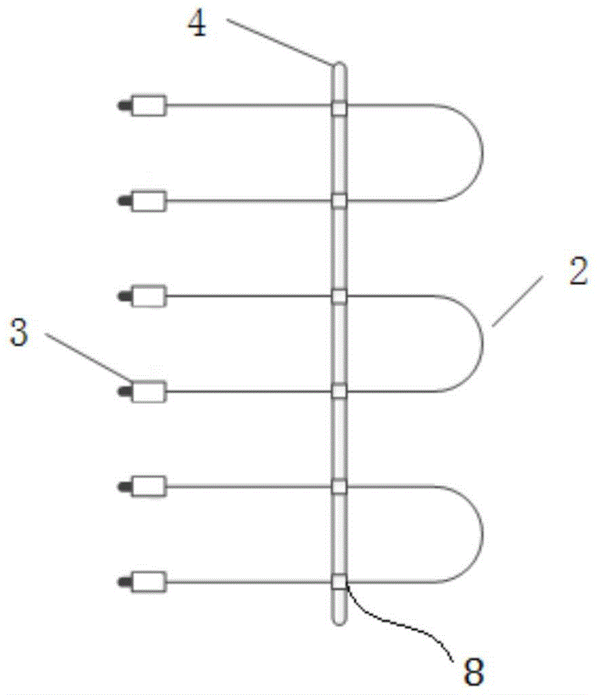
[0043] S1: Utilize the optical cable optical fiber serial connection detection device described in embodiment 1 to carry out the end-to-end connection of the optical cable optical fibers to be tested, such as Figure 4 As shown, at one end of the optical cable 7, use the optical fiber serial connection detection device to start from the first optical fiber to perform two jumps on the optical distribution 5 in sequence. According to this method, all the optical fibers to be tested can be jumped at one time. To simplify the description As shown in the figure, in this embodiment, only six optical fibers of one optical cable are tested in series. At the other end of the optical cable 7, which is the test end, start from the second optical fiber of the optical cable 7 and perform two jumps on the optical distribution 5 in sequ...


PUM


Abstract

The invention provides an optical cable fiber series connection detection device and method. One end of a fiber to be tested, a jump fiber and other fibers to be tested are connected in a head-to-tail way via a fiber connector. One end of the optical cable fiber is tested by utilizing an optical time domain reflectometer so that an optical path test curve is acquired. Data parameters of the optical cable fiber are acquired according to the optical path test curve so that multiple fibers can be detected simultaneously, a problematic fiber can be rapidly positioned, and thus time consumption is low and efficiency is high. Besides, a tail fiber does not need to be externally connected in detection of each fiber for elimination of influence of a blind area so that detection time is further increased, detection efficiency is enhanced, and thus performance of a bidirectional test on middle connecting points and joints of the two ends of the optical cable fiber is facilitated.

Description

technical field [0001] The invention relates to the technical field of optical communication, in particular to a device and method for detecting optical fiber serial connections of optical cables. Background technique [0002] The optical cable network is the cornerstone of modern information transmission. With the progress of my country's informatization construction, a large number of optical cable erections are carried out. In order to ensure the quality of communication facilities and the smooth opening of communication services in the future, it is necessary to inspect the completed optical cables. Data such as loss and joint loss are tested, and these data can be used as important information for future operation and maintenance. [0003] At present, the most widely used optical cable detection methods are absolute power measurement method and backscattering method. The absolute power measurement method is mainly to measure the total attenuation of the fiber core of th...

Claims


Application Information

Patent Timeline
Patent Type & Authority Applications(China)
IPC IPC(8): H04B10/071
Inventor 孟建黄彦李凯彭碧君
Owner STATE GRID SHANDONG ELECTRIC POWER
Learn More