Endoscope device

An endoscope and lens technology, applied in the field of endoscope devices, can solve the problems of not considering the applicable optical system, etc., and achieve the effect of easy miniaturization and high-precision change

Active Publication Date: 2014-10-22
FUJIFILM CORP
View PDF6 Cites 4 Cited by
  • Summary
  • Abstract
  • Description
  • Claims
  • Application Information

AI Technical Summary

Problems solved by technology

[0008] The technology of Patent Document 1 is mainly applicable to video cameras, and application to very small optical systems such as endoscope devices is not considered.

Method used


Image

  • Endoscope device
  • Endoscope device
  • Endoscope device

Examples


Embodiment Construction

[0037] Hereinafter, embodiments of the present invention will be described with reference to the drawings.

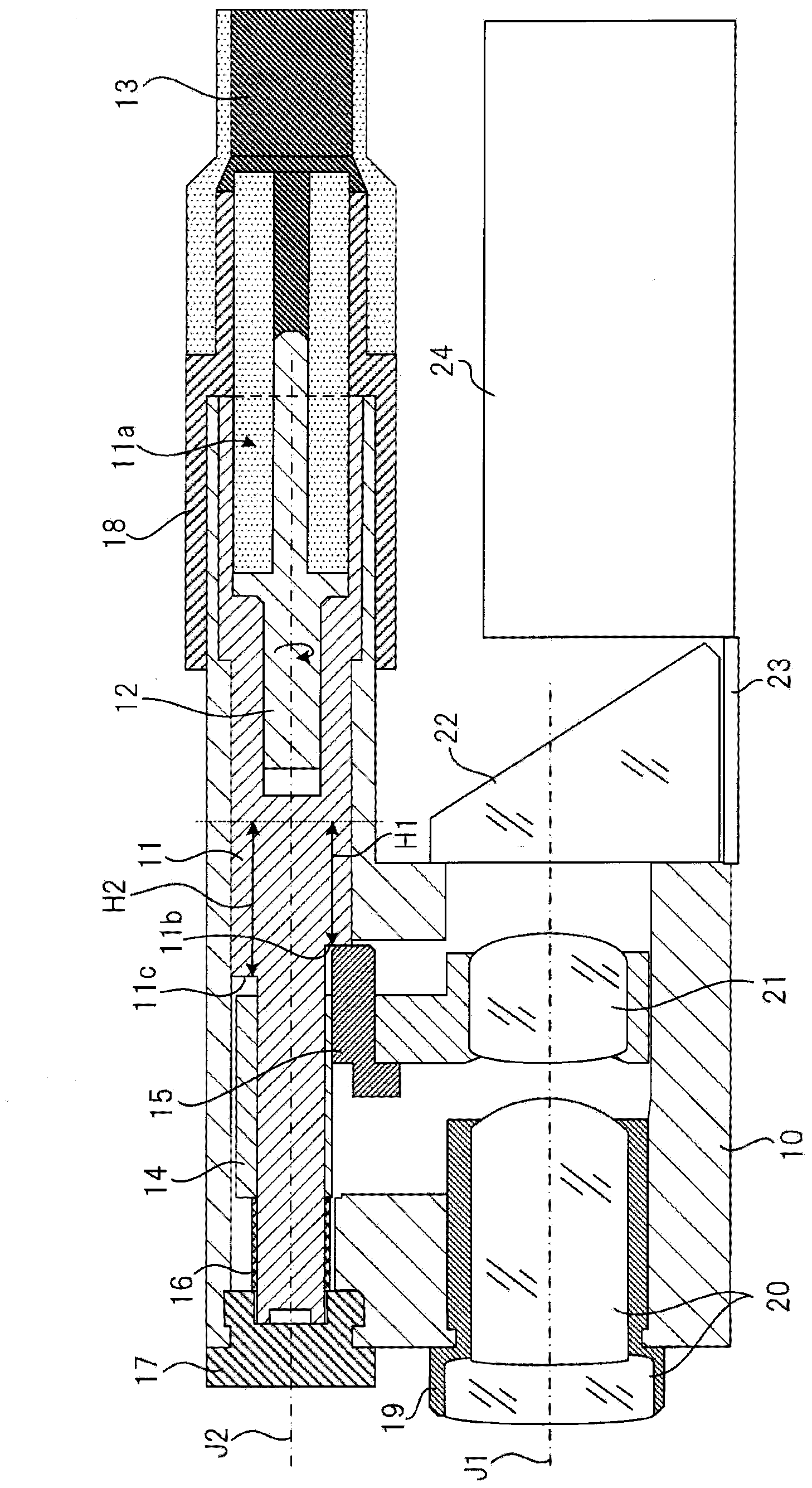
[0038] figure 1 It is a cross-sectional view illustrating a schematic configuration of an imaging device positioned at a distal end portion of a probe of an endoscope device according to an embodiment of the present invention.

[0039] The endoscope device includes a lens group including an objective lens 20 and a movable lens 21, and a CCD (Charge Coupled Device) type or CMOS (Complementaly Metal Oxide Semiconductor) type imaging element 23 for imaging a subject through the lens group. .

[0040] The objective lens 20 is a lens whose position is fixed in the direction in which the optical axis J1 of the lens group extends (hereinafter referred to as the optical axis direction). The objective lens 20 consists of at least one lens. The objective lens 20 is held by a holding member 19 fixed to the housing 10 .

[0041] The movable lens 21 is a lens for switching a fo...


PUM


Abstract

The invention provides an endoscope device which can be easily made to be miniature and enables the focus distance to be changed in a highly precise manner. The endoscope device comprises a shooting element (23) which shoots an object to be shot through a lens unit including a movable lens (21). The endoscope device is equipped with a rotation component (11) that rotates freely with a rotation shaft (J2) being the center; a motor that drives the rotation component (11) to rotate; a movable lens retaining portion (14) that has a pin (15) abutting against part (11B) of the rotation component (11) and that retains the movable lens (21); and a spring (16) that applied force to the pin (15) toward the rotation component (11). The rotation component (11) includes a cylindrical part (11B) extending in the direction of an optical axis; and a cylindrical part (11A) protruding from the transverse plane of the part (11B) at the side of the object to be shot and thinner than the part (11B). The transverse plane of the part (11B) includes an abut surface (11d) which abuts against the pin (15) and continuously changes, in terms of the height in the direction of the optical axis, along the circumference of the part (11B). The movable lens retaining portion (14) is freely embedded into the part (11A) in a movable manner in the direction of the optical axis.

Description

technical field [0001] The present invention relates to endoscopic devices. Background technique [0002] Known are endoscope devices equipped with a pan-focus imaging device capable of focusing from a near point to a far point, and endoscope devices equipped with an imaging device capable of changing a focal length to obtain a magnified image during close-up observation. [0003] For endoscopic devices with variable focal length, such as Figure 8 The camshaft 81 is widely used as a drive mechanism as shown in the sectional view of the imaging device positioned at the tip of the probe of the endoscope device. According to this imaging device, the rotational driving force of the motor M is transmitted to the camshaft 81 via the gear 83, the intermediate shaft 85, and the like to drive the camshaft 81 to rotate. Lens holding members 91 , 93 holding the lenses 87 , 89 are pivotally supported on the cam shaft 81 , and have pins 99 , 101 inserted into the cam grooves 95 , 97 . ...

Claims


Application Information

Patent Timeline
IPC IPC(8): G02B23/24G02B7/04
Inventor 北野亮
Owner FUJIFILM CORP
Why Eureka
Try Eureka