Unmanned aerial vehicle capable of performing monitoring shooting and controlling through smart glasses

A technology for smart glasses and drones, applied in the field of drones, can solve problems such as misoperation, poor vision, misjudgment, etc., and achieve the effects of convenient use, fewer misoperations, and good control effects.

Active Publication Date: 2014-10-22
山西超鹰科技有限公司
6 Cites 30 Cited by

AI-Extracted Technical Summary

Problems solved by technology

[0004] Surveillance shooting is an important function of UAVs. UAVs with monitoring functions can be used in a series of fields such as home entertainment, exploration, scientific research, and military reconnaissance. In order to facilitate remote control of UAVs, it is mainly through the front of UAVs. The camera transmits the surrounding images to the display screen of the corresponding control co...

Method used

The present invention designs a kind of unmanned aerial vehicle that can be monitored, photographed and controlled by smart glasses, which combines 3D forming technology with unmanned aerial vehicle technology and smart glasses technology, and sets a double The head camera uses the smart glasses ...

Abstract

An unmanned aerial vehicle capable of performing monitoring shooting and controlling through smart glasses comprises an unmanned aerial vehicle body, a camera seat, a control bracket, the smart glasses and a controller, wherein the camera seat is fixed below a front end of the unmanned aerial vehicle body through the control bracket, a pair of unmanned aerial vehicle signal emitting and receiving devices is arranged at the front end of the unmanned aerial vehicle body, the smart glasses comprise a smart glasses body, supporting legs, supporting leg connection hinges, a smart glasses signal emitting and receiving device, a button, a glasses frame bracket for a display screen, the display screen, a columnar image projector, an eyeball position inductor, a bracket connection hinge and an inductor fixing bracket, and the controller corresponds to the unmanned aerial vehicle signal emitting and receiving devices through a built-in signal emitting and receiving device. According to the unmanned aerial vehicle, three-dimensional (3D) imaging technology and unmanned aerial vehicle and smart glasses technology are combined, users may feel immersive, control effects are better by means of a wristband for controlling, framing authenticity is high, the whole device is easy to carry, and real monitoring effects on the unmanned aerial vehicle can be achieved when the users stand on the ground.

Application Domain

Technology Topic

Image

  • Unmanned aerial vehicle capable of performing monitoring shooting and controlling through smart glasses
  • Unmanned aerial vehicle capable of performing monitoring shooting and controlling through smart glasses
  • Unmanned aerial vehicle capable of performing monitoring shooting and controlling through smart glasses

Examples

  • Experimental program(1)

Example Embodiment

[0039] The following describes the invention in detail with reference to the drawings and embodiments:
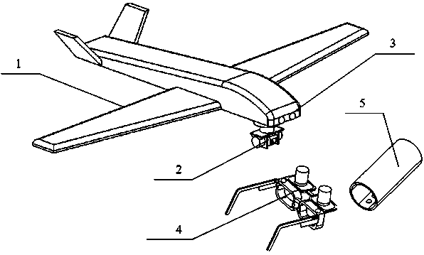
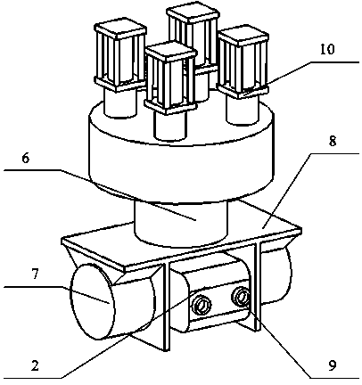
[0040] The present invention designs a drone that can be monitored, photographed and controlled by smart glasses. It combines 3D shaping technology with drone technology and smart glasses technology, and a dual-head camera with high freedom is set at the bottom of the drone. Use smart glasses to get the corresponding three-dimensional patterns, so as to give people an immersive feeling, and then control them through the bracelet, so that the control effect is good, the viewing accuracy is high, and the entire device is easy to carry, and people can realize the The real monitoring effect on the drone.
[0041] As an embodiment of the present invention, the present invention provides a drone capable of monitoring, shooting and controlling through smart glasses, including a drone body 1, a camera base 2, a control bracket, smart glasses, and a controller:
[0042] The camera mount 2 of the present invention is fixed below the front end of the drone body 1 through a control bracket. There is a pair of cameras 9 in front of the camera mount 2. The control bracket includes a main rotating motor 6, a side rotating motor 7, and a bracket 8. The bottom of the main rotating motor 6 is fixed below the front end of the drone body 1, the end of the rotating shaft of the main rotating motor 6 has a bracket 8, and the two sides of the camera base 2 are respectively connected to the rotating shafts of the side rotating motors 7. The bottom of the side rotating motor 7 is fixed on the lower end surface of the bracket 8, and the front end of the drone body 1 has a pair of drone signal transmitter receivers 3;
[0043] The smart glasses of the present invention include a smart glasses main body 4, a supporting leg 11, a supporting leg connecting hinge 12, a smart glasses signal transmitter and receiver 14, a button 15, a display frame bracket 16, a display screen 17, a cylindrical image projector 18, and eyeball position The sensor 19 and the bracket are connected to the hinge 20 and the sensor fixing frame 21. The smart glasses body 4 has two frames, the feet 11 have a pair, and one end of the feet 11 is connected to the side of the hinge 12 and the smart glasses body 4 through the feet. Each of the smart glasses body 4 has a smart glasses signal transmitter receiver 14 corresponding to the drone signal transmitter receiver 3 at the front end of the drone body 1, and the eyeball position sensor 19 passes The sensor fixing frame 21 is fixed in the lens frame of the smart glasses body 4, the lens of the eyeball position sensor 19 faces the eyeball side, and the display screen lens frame bracket 16 has two lens frames corresponding to the lens frames of the smart glasses body 4. , There is a display screen 17 in the frame of the display screen frame support 16, and a columnar image projector 18 is fixed to the display screen 17, and the lens of the columnar image projector 18 rests on the display screen 17. The upper end of the screen frame bracket 16 is connected to the upper end of the smart glasses main body 4 through a bracket connecting hinge 20, and a button 15 is provided on the leg 11;
[0044] The controller of the present invention corresponds to the UAV signal transmitter receiver 3 through the built-in signal transmitter receiver.
[0045] As a preferred embodiment of the present invention, the present invention provides figure 1 Shown is an unmanned aerial vehicle that can be monitored, photographed and controlled through smart glasses, including a drone body 1, a camera base 2, a control bracket, smart glasses and a controller:
[0046] The camera holder 2 of the present invention is such as figure 2 As shown, the control bracket is fixed below the front end of the drone body 1, and there is a pair of cameras 9 in front of the camera mount 2. The control bracket is image 3 Shown includes a main rotating motor 6, a side rotating motor 7, and a bracket 8. The drone body 1 has a slot below the front end, and the drone body 1 has a telescopic cylinder 4 in the slot below the front end. The bottom of the cylinder 4 is fixed in the groove below the front end of the drone body 1, and the end of the telescopic rod of the telescopic cylinder 4 is connected to the bottom of the main rotating motor 6. The telescopic cylinder can be used when the camera is not used. The inside of the machine does not affect the landing. There are 4 telescopic cylinders 4 divided into 2 rows. In order to ensure the stability of the camera contraction, a plurality of telescopic cylinders need to be provided. The end of the rotating shaft of the main rotating motor 6 has a bracket 8. The two sides of the camera base 2 are respectively connected with the rotating shaft of the side rotating motor 7, the bottom of the side rotating motor 7 is fixed on the lower end surface of the bracket 8, and the front end of the drone body 1 has a pair of drone signal transmitter receivers 3;
[0047] The smart glasses of the present invention are Figure 4 with 5 Shown includes smart glasses main body 4, legs 11, leg connecting hinges 12, smart glasses signal transmitter and receiver 14, buttons 15, frame bracket for display screen 16, display screen 17, cylindrical image projector 18, eye position sensor 19, The bracket is connected to the hinge 20 and the sensor fixing frame 21. The smart glasses body 4 has two frames. The frames of the smart glasses body 4 are equipped with lenses. The frames of the present invention can be provided with a frame holder for the display screen when not in use. Open for use as ordinary glasses, the legs 11 have a pair, one end of the legs 11 is connected to the side end of the smart glasses body 4 through a leg connecting hinge 12, and the smart glasses body 4 has a smart glasses signal transmitter on each frame The receiver 14 corresponds to the drone signal transmitter 3 at the front end of the drone body 1, the eye position sensor 19 has a pair, and the eye position sensor 19 is symmetrically fixed to the smart glasses through the sensor fixing frame 21 A pair of eyeball position sensors can be provided on the upper and lower end surfaces of the lens frame of the main body 4 in order to accurately position the eyeballs. The lens of the eyeball position sensor 19 faces the eyeball side, and the display frame bracket 16 has 2 Two spectacle frames correspond to the spectacle frame of the smart glasses main body 4. The spectacle frame bracket 16 for the display screen has a display screen 17 in the spectacle frame, and the display screen 17 is fixed with a cylindrical image projector 18, the cylindrical image projector 18 The lens rests on the display screen 17, the upper end of the display frame bracket 16 is connected to the upper end of the smart glasses main body 4 through the bracket connecting hinge 20, the support foot 11 has a button 15 and the button 15 on the support foot 11 is for camera Buttons, camera buttons, switch buttons, and focus buttons. The present invention can set corresponding camera buttons, camera buttons, switch buttons, and focus buttons according to functions. There is a camera below the end of the leg 11 connected to the smart glasses body 4 The touch screen 13 is controlled, and the touch screen is controlled by the camera under the feet, which can facilitate the operator to hold the glasses for control, the operation is extremely convenient, and it can be operated separately from the drone.
[0048] The controller of the present invention is Image 6 The touch control ring shown includes a control ring main body 5, a touch screen 22, and a connecting buckle 23. The control ring main body 5 has a built-in signal transmitter receiver, the control ring main body 5 has an opening, and the control ring main body 5 has an opening. The two ends of the opening are connected by a connecting buckle 23. The control ring main body 5 has a touch screen 22. The touch control ring of the present invention can adopt the above structure, so that it can be better placed on the arm. The controller is connected with the built-in signal transmitter and receiver. The UAV signal transmitter receiver 3 corresponds to it,
[0049] The controller of the present invention is a remote controller or a control ring. The controller of the present invention can use a remote controller or a control ring. The control ring can be directly placed on the arm to control the drone, and the operation is more convenient. The control ring is a button-type control ring or a touch-type control ring. The control ring of the present invention can be a button-type or a touch-screen type. The touch-screen type is more convenient to operate, but the touch-screen is easy to be damaged when used regularly. The life span is longer.
[0050] The above are only preferred embodiments of the present invention, and are not intended to limit the present invention in any other form. Any modification or equivalent change made according to the technical essence of the present invention still belongs to the scope of protection claimed by the present invention. .

PUM

no PUM

Description & Claims & Application Information

We can also present the details of the Description, Claims and Application information to help users get a comprehensive understanding of the technical details of the patent, such as background art, summary of invention, brief description of drawings, description of embodiments, and other original content. On the other hand, users can also determine the specific scope of protection of the technology through the list of claims; as well as understand the changes in the life cycle of the technology with the presentation of the patent timeline. Login to view more.

Similar technology patents

Adaptive canceller for frequency reuse systems

ActiveUS6859641B2Effective and efficient mannerEasy to useRadio transmissionTransmission noise suppressionSignal of interestSatellite
Owner:RAYTHEON APPLIED SIGNAL TECH

Utilization of podcasts on portable media devices

InactiveUS20060265637A1Easy to useDigital data information retrievalUsing non-detectable carrier informationMediaFLOMetadata
Owner:APPLE INC

Classification and recommendation of technical efficacy words

  • Easy to use
  • Good control effect

Laser assisted total joint arthroplasty

InactiveUS20090234360A1Easy to useNon-surgical orthopedic devicesSurgical sawsLaser assistedLaser guidance
Owner:ALEXANDER VLADIMIR

System, method, and apparatus for settlement for participation in an electric power grid

ActiveUS8583520B1Communication securityEasy to useLevel controlCoin-freed apparatusNetwork managementGrid operator
Owner:CAUSAM ENERGY INC

Multi-channel active noise control system for power transformer

InactiveCN102208263AGood control effectGood channel expansionTransformers/inductances noise dampingEnvironmental noiseTransformer
Owner:NANJING UNIV
Why Eureka
Try Eureka