A method to solve the problem of TSV delamination and copper surface depression after cmp

A through-silicon via and copper surface technology, applied in the field of through-silicon via process integration solutions, can solve problems such as unevenness, reliability analysis failure, and device failure

Active Publication Date: 2017-07-14
SEMICON MFG INT (SHANGHAI) CORP
View PDF4 Cites 0 Cited by
  • Summary
  • Abstract
  • Description
  • Claims
  • Application Information

AI Technical Summary

Problems solved by technology

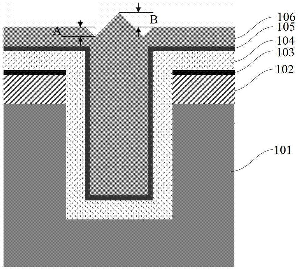
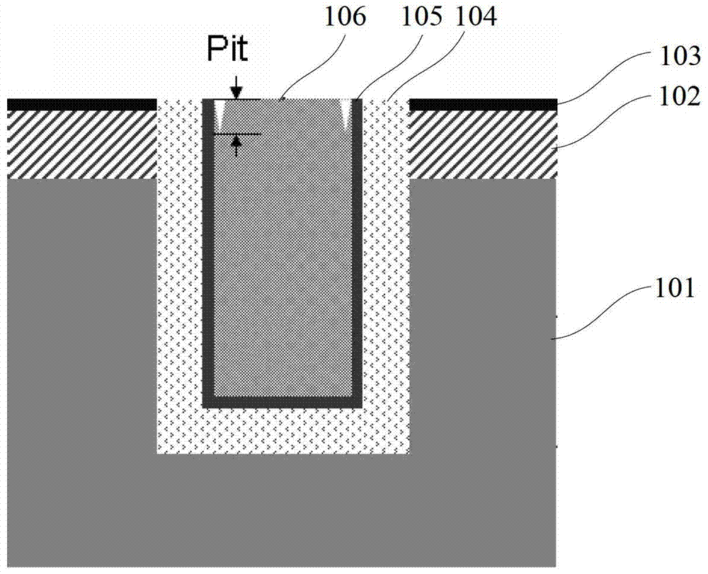
[0006] The first problem is that there are gaps (Pits) between the copper and the barrier layer after CMP, and the TSV on the edge of the silicon wafer also has the phenomenon that the entire copper surface is concave and uneven
Depositing a metal layer covering TSVs in the back-end process cannot protect TSVs uniformly and continuously
If there is a crack, the copper in the TSV will diffuse out through the crack, and the chemical that corrodes the copper will corrode the copper and continue to the inside of the TSV, forming a void in the upper part of the TSV, causing the device to fail
[0007] The second problem is that the layers of thin films deposited on the side walls of TSVs have different thermal expansion coefficients, and delamination (Delamination or Crack) occurs in subsequent processes, resulting in failure of reliability analysis.

Method used

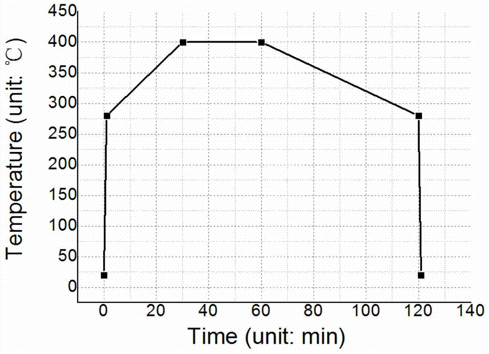

Image

  • A method to solve the problem of TSV delamination and copper surface depression after cmp
  • A method to solve the problem of TSV delamination and copper surface depression after cmp
  • A method to solve the problem of TSV delamination and copper surface depression after cmp

Examples


Embodiment Construction

[0038] Embodiments of the present invention are described below through specific examples, and those skilled in the art can easily understand other advantages and effects of the present invention from the content disclosed in this specification. The present invention can also be implemented or applied through other different specific implementation modes, and various modifications or changes can be made to the details in this specification based on different viewpoints and applications without departing from the spirit of the present invention.

[0039] see Figure 4 ~ Figure 6 . It should be noted that the diagrams provided in this embodiment are only schematically illustrating the basic idea of ​​the present invention, and only the components related to the present invention are shown in the diagrams rather than the number, shape and shape of the components in actual implementation. Dimensional drawing, the type, quantity and proportion of each component can be changed arbitr...


PUM


Abstract

The invention provides a scheme for solving the copper surface indentation problem after silicon through hole layering and CMP. The scheme comprises the following steps: 1) a silicon through hole is formed in a silicon substrate of which the surface is provided with a stop layer, a silicon dioxide isolation layer is deposited on surfaces of the silicon through hole and the silicon substrate, and a barrier layer and a seed layer are formed on the surface of the silicon dioxide isolation layer; 2) copper is electroplated onto the surface of the seed layer to form copper for at least filling the silicon through hole; 3) the anneal process is performed on the structure, wherein the anneal process comprises the following steps: 3-1) the temperature rises from the room temperature to 80-200 DEG C with a speed of 0.5-5 DEG C / min, and is maintained for 0-60 min; 3-2) the temperature rises to 250-450 DEG C with a speed of 1-10 DEG C / min, and is maintained for 15-180min; 3-3) and the temperature is reduced to 25-100 DEG C with a speed of 1-5 DEG C / min; 4) and polishing is performed through the chemico-mechanical polishing CMP until the stop layer is exposed. According to the invention, by improving the silicon substrate baking process and the copper anneal process, the layering phenomenon in the silicon through hole process can be effectively eliminated, and the copper surface indentation problem after the CMP can be solved, the method has simple steps, the process cost will not be increased, and the scheme is suitable for being used in industry production.

Description

technical field [0001] The invention relates to a process integration scheme of through-silicon holes, in particular to a scheme for solving the delamination problem of the sidewall multilayer film structure of the through-silicon hole and the problem of gaps or even depressions on the copper surface after CMP. Background technique [0002] Stacking chips in three dimensions and vertical interconnects through silicon wafers or chips allows integrated circuits to evolve beyond Moore's Law. Through Silicon Via (TSV) is the core technology of interlayer vertical interconnection. Two essential technologies supporting TSV technology are wafer thinning and bonding. The main application directions of the three-dimensional stacking technology of chips include: 1) The three-dimensional packaging technology reduces the size of the package, thereby reducing the production cost; A complete microcircuit system; 3) The same kind of circuit can also be divided and stacked, such as stacki...

Claims


Application Information

Patent Timeline
Patent Type & Authority Patents(China)
IPC IPC(8): H01L21/768
CPCH01L21/7684H01L21/76898
Inventor 孙丰达
Owner SEMICON MFG INT (SHANGHAI) CORP
Why Eureka
Try Eureka