Supercharge Your Innovation With Domain-Expert AI Agents!

Fuel injectors for turbomachines

A technology of fuel injector and turbine engine, applied in the fuel valve of turbine/propulsion device, fuel control of turbine/propulsion device, fuel flow passage of turbine/propulsion device, etc., can solve the problem of harmful, uneven performance of turbine engine, etc. question

Active Publication Date: 2016-05-04
SN DETUDE & DE CONSTR DE MOTEURS DAVIATION S N E C M A
View PDF7 Cites 0 Cited by
  • Summary
  • Abstract
  • Description
  • Claims
  • Application Information

AI Technical Summary

Problems solved by technology

[0011] However, this leakage will be present in the entire operating range of the turbine engine, i.e. not only during start-up and when working at low power, but also at full power, and it will create inhomogeneities in the combustion chamber, which will have a negative effect on the turbine engine performance will be detrimental to

Method used


Image

  • Fuel injectors for turbomachines
  • Fuel injectors for turbomachines
  • Fuel injectors for turbomachines

Examples


Embodiment Construction

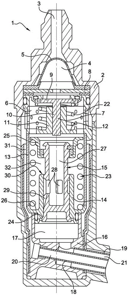
[0027] figure 1 The fuel injector 1 disclosed in the patent application FR2832492 in the applicant's name is shown in .

[0028] This injector 1 is of the aerodynamic type and comprises a primary fuel circuit, for example, for use during start-up and low power phases, and a secondary fuel circuit, which participates in addition to the primary circuit at medium and high power subsequent during the work phase.

[0029] The injector 1 has a hollow body 2 with a fuel inlet 3 for receiving fuel under pressure from a fuel pump (not shown) and opening into a pre-feed chamber 4 after passing through a strainer 5 .

[0030] The body 2 also has a feed chamber 6 downstream of the pre-feed chamber 4 (in the flow direction of the fuel through the injector) and separated therefrom by a shut-off valve 7 . A partition 8 is placed between the pre-feed chamber 4 and the shut-off valve 7 .

[0031] The shut-off valve 7 has a head 9 and a stem 10 mounted movably in a tubular portion 11 of an a...


PUM


Abstract

The invention relates to a fuel injector for a turbomachine comprising a body comprising a primary fuel circuit fed by a metering valve (15) and a secondary fuel circuit. Leakage channels (36, 37, 38) extend from the area (32) fluidly connected to the primary circuit to the area (17) fluidly connected to the secondary circuit. The leakage channel (36, 37, 38) is intended to be opened in the closed position of the metering valve (15) and to be closed by movement of the metering valve (15).

Description

technical field [0001] The present invention relates to a fuel injector for a turbine engine, such as an aircraft turboprop or turbojet. Background technique [0002] A turbine engine generally comprises an annular combustion chamber having fuel injectors regularly distributed at its upstream end and means for supplying air around the injectors. [0003] There are two main types of injectors, the so-called "aerodynamic" injectors, which have two fuel circuits, providing the fuel to match the different operating phases of the turbine engine (starting phase, at low power or at full power) The fuel flow rate, and the so-called "aerodynamic" injectors, which have only one fuel circuit, are used for all working phases of the turbine engine. [0004] Patent application FR2832492 in the applicant's name describes an injector of the aerodynamic type, with a primary fuel circuit, for example, for starting and for low power phases, and a secondary circuit, which participates in addit...

Claims


Application Information

Patent Timeline
IPC IPC(8): F02C7/232F02C9/26F23D11/26F23K5/14
CPCF23K5/147F23D11/26F23D2900/00016F23D2214/00F23N2235/24F02C7/232F02C7/22F02C9/263F02C7/222F23R3/28
Inventor 乔斯·罗纳德·罗德里格斯埃米莉·夏洛特·波赛
Owner SN DETUDE & DE CONSTR DE MOTEURS DAVIATION S N E C M A
Features
  • R&D
  • Intellectual Property
  • Life Sciences
  • Materials
  • Tech Scout
  • Unparalleled Data Quality
  • Higher Quality Content
  • 60% Fewer Hallucinations
Learn More