Detection device and method for olefin gas

A detection device and detection method technology, applied in the direction of transmittance measurement, etc., can solve problems such as safety accidents and production losses, and achieve the effect of accurate cost

Inactive Publication Date: 2014-10-29
GR APPL TECH
View PDF9 Cites 6 Cited by
  • Summary
  • Abstract
  • Description
  • Claims
  • Application Information

AI Technical Summary

Problems solved by technology

[0005] In chemical production sites, olefin gas leakage detection is very important. If there is olefin gas leakage without detection and alarm, safety accidents will occur. However, if some gases suspected of olefin cannot be detected accurately, false alarms will bring losses to production.

Method used


Image

  • Detection device and method for olefin gas
  • Detection device and method for olefin gas
  • Detection device and method for olefin gas

Examples


Embodiment 1

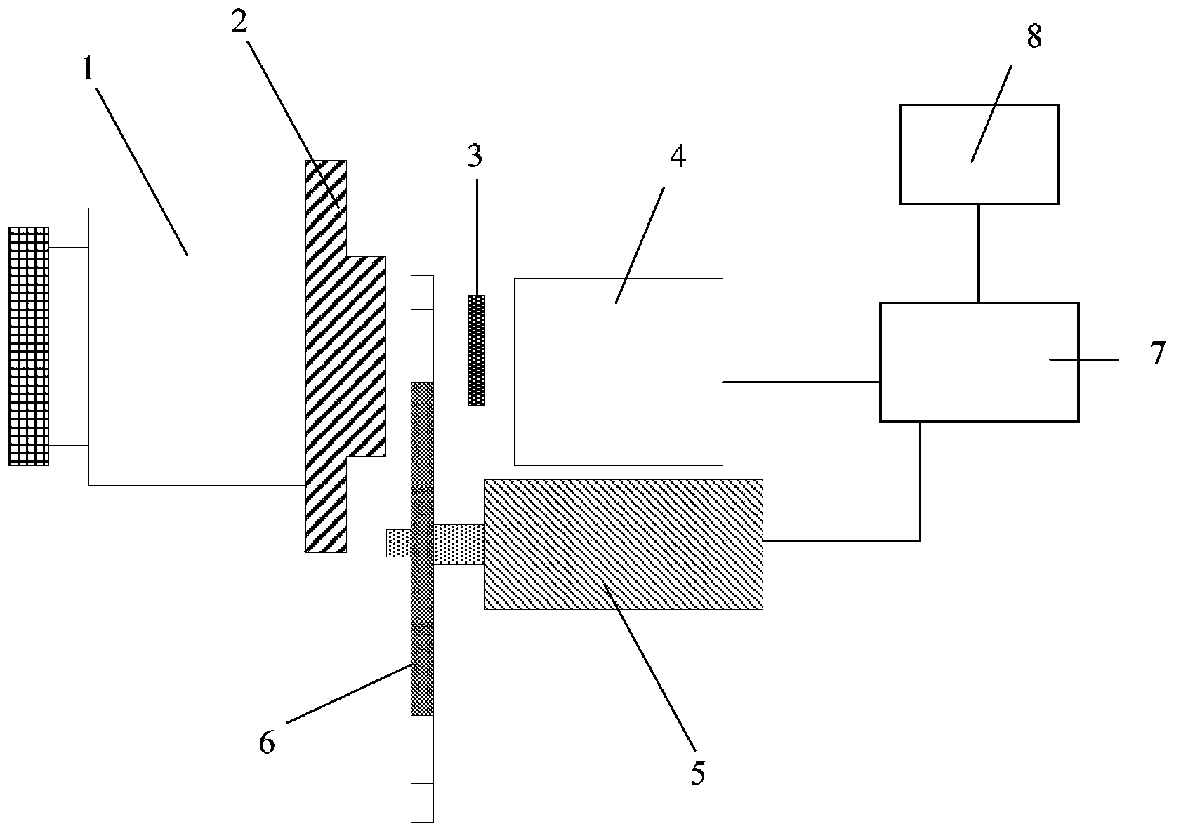
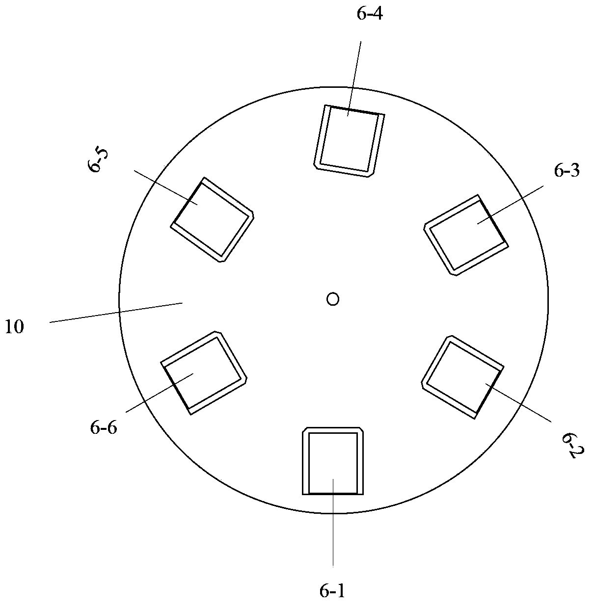
[0034] This embodiment discloses a detection device and detection method for olefin gas, figure 1 It is a schematic structural diagram of the detection device for olefin gas in this embodiment. Such as figure 1 As shown, the detection device includes an infrared lens 1 , a lens interface 2 , an olefin gas identifier 6 , an infrared detector 3 , a processing circuit 4 , an encoding motor 5 , a monitoring and analysis unit 7 , and a display 8 . The infrared lens 1 is used to focus the infrared radiation signal of the gas in the environment to be measured and the background. The olefin gas identifier is arranged between the infrared lens 1 and the infrared detector 3. The olefin gas identifier includes a turntable 10 and an Olefin bandpass filters and blackbody windows. figure 2 It is a top view structure schematic diagram of the olefin gas identifier 6 .

[0035] The turntable 10 of the olefin gas identifier 6 is provided with: a blackbody window 6-1, a first olefin bandpass...

Embodiment 2

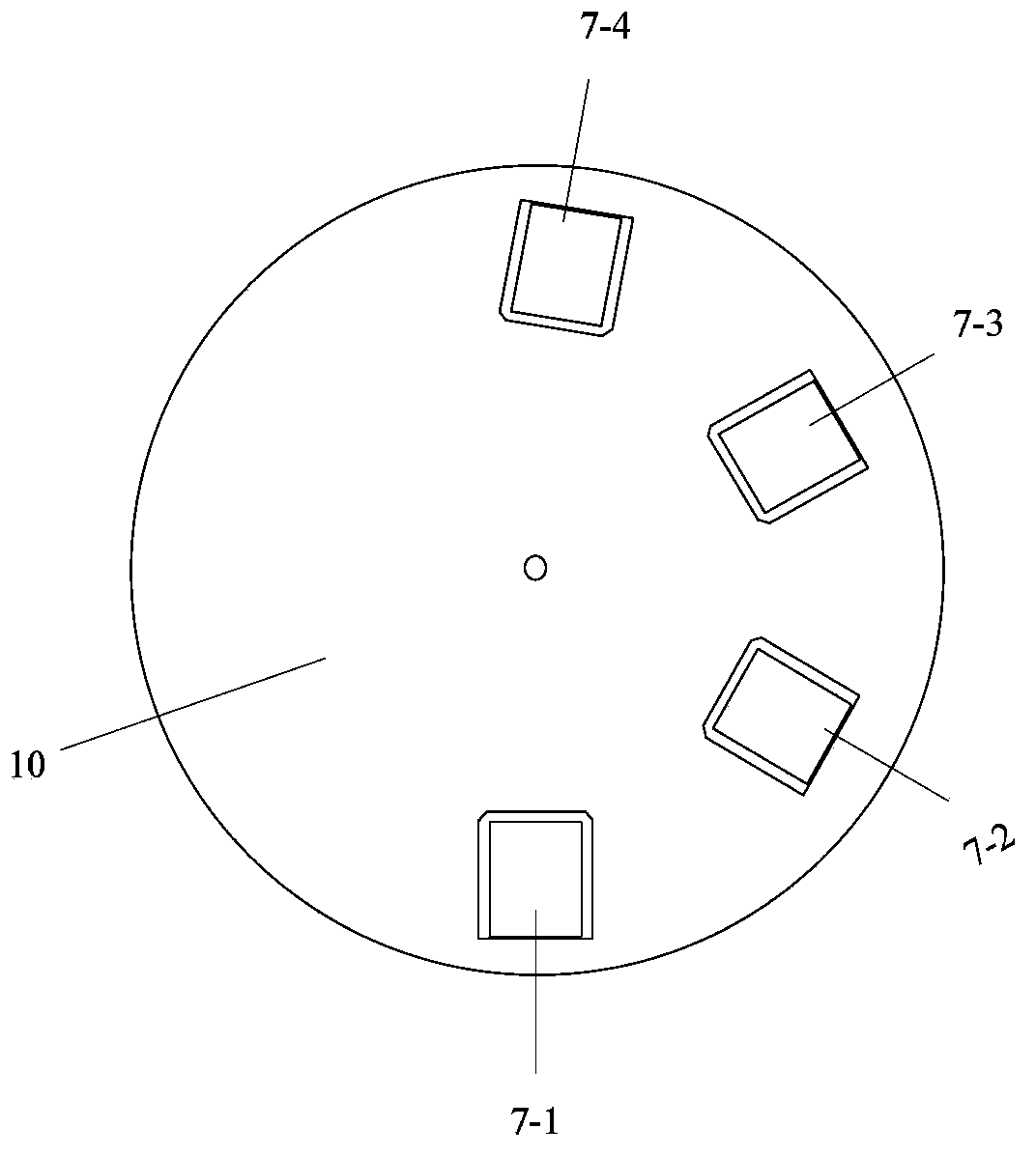
[0049] This embodiment discloses another olefin gas detection device and detection method. The detection device includes an infrared lens, a lens interface, an olefin gas identifier, an infrared detector, a processing circuit, an encoding motor, a monitoring and analysis unit, and a display. These are the same as those in the first embodiment, except that three olefin bandpass filters are arranged on the turntable of the olefin gas identifier. image 3 It is a schematic diagram of the top view structure of the olefin gas identifier.

[0050] The turntable of the olefin gas identifier includes: black body window 7-1, the first olefin bandpass filter 7-2, its center wavelength is 10.1 ± 0.020 microns, the second olefin bandpass filter 7-3, its center wavelength is 10.99±0.02 microns, and the third olefin bandpass filter 7-4 has a central wavelength of 12.28±0.02 microns. image 3 Fig. 1 schematically shows the distribution of the three olefin bandpass filters on the turntable ...

Embodiment 3

[0062] This embodiment discloses another olefin gas detection device and detection method. The detection device includes an infrared lens, a lens interface, an olefin gas identifier, an infrared detector, a processing circuit, an encoding motor, a monitoring and analysis unit, and a display. These are the same as those in the first embodiment, except that two olefin bandpass filters are arranged on the turntable of the olefin gas identifier. Figure 4 It is a schematic diagram of the top view structure of the olefin gas identifier.

[0063] The turntable of the olefin gas discriminator includes a blackbody window 8-1, a first olefin bandpass filter 8-2 with a center wavelength of 3.24 ± 0.02 microns, and a second olefin bandpass filter 8-3 with a center wavelength of 3.31 ± 0.02 microns. The passband lengths of the two olefin bandpass filters are both 100±20nm. The olefin bandpass filter selected in this embodiment is a medium-wave filter, and correspondingly, the infrared ...


PUM

PropertyMeasurementUnit
wavelengthaaaaaaaaaa

Abstract

The invention provides a detection device and method for an olefin gas. The detection device includes: an infrared optical lens, which is used for focusing infrared radiation signals; an olefin gas recognizer, which includes a turntable and at least one olefin band pass filter plate disposed on the turntable; an infrared detector, which is used for converting infrared radiation signals passing through the olefin band pass filter plate into voltage signals so as to form an infrared image; a monitoring and analysis unit, which is used for acquiring and analyzing the infrared image, outputting the analysis result, and controlling the turntable of the olefin gas recognizer according to the analysis result; and a display, which is connected to the output end of the monitoring and analysis unit and is used for displaying the output result. Compared with the prior art, the olefin gas detection device and method provided by the invention are based on an infrared imaging technology, and can visually judge whether a to-be-detected target is an olefin gas accurately and quickly.

Description

technical field [0001] The invention relates to a gas detection device and method, in particular to an olefin gas detection device and method. Background technique [0002] The harm caused by olefinic gases to the environment has attracted people's attention. In chemical plants, the leakage of olefin gases will bring serious harm, affect production, and may cause safety accidents, directly threatening human safety. Therefore, the detection of olefin gases in chemical plants has always been widely valued by people. . [0003] The traditional olefin detection method is mainly the fluorescence indicator adsorption method, which requires cumbersome sample collection and pretreatment procedures, is time-consuming and laborious, cannot achieve online analysis, and the detection sensitivity is not high enough. The Chinese patent with the publication number CN101551358A discloses a method for highly sensitive detection of alkanes, alkenes and halogenated alkanes, using glow discha...

Claims


Application Information

Patent Timeline
Patent Type & Authority Applications(China)
IPC IPC(8): G01N21/61
Inventor 陈祥初张力黄晓家孟思齐王明会王军
Owner GR APPL TECH
Why Eureka
Try Eureka