Unmanned aerial vehicle flight control system architecture based on TTP/C bus

A flight control system and unmanned aerial vehicle technology, applied in the field of flight control, can solve the problems of lack of openness and modularity, poor reliability, and low real-time performance.

Active Publication Date: 2014-10-29
CHENGDU AIRCRAFT DESIGN INST OF AVIATION IND CORP OF CHINA
View PDF5 Cites 26 Cited by
  • Summary
  • Abstract
  • Description
  • Claims
  • Application Information

AI Technical Summary

Problems solved by technology

[0004] From the development of UAV technology in various military powers, it can be seen that UAVs show obvious characteristics of multi-tasking, long endurance, high maneuverability, and high dynamics, and gradually begin to replace the tasks and functions of some manned aircraft. The development characteristics have put forward strict requireme

Method used


Image

  • Unmanned aerial vehicle flight control system architecture based on TTP/C bus
  • Unmanned aerial vehicle flight control system architecture based on TTP/C bus

Examples


Embodiment Construction

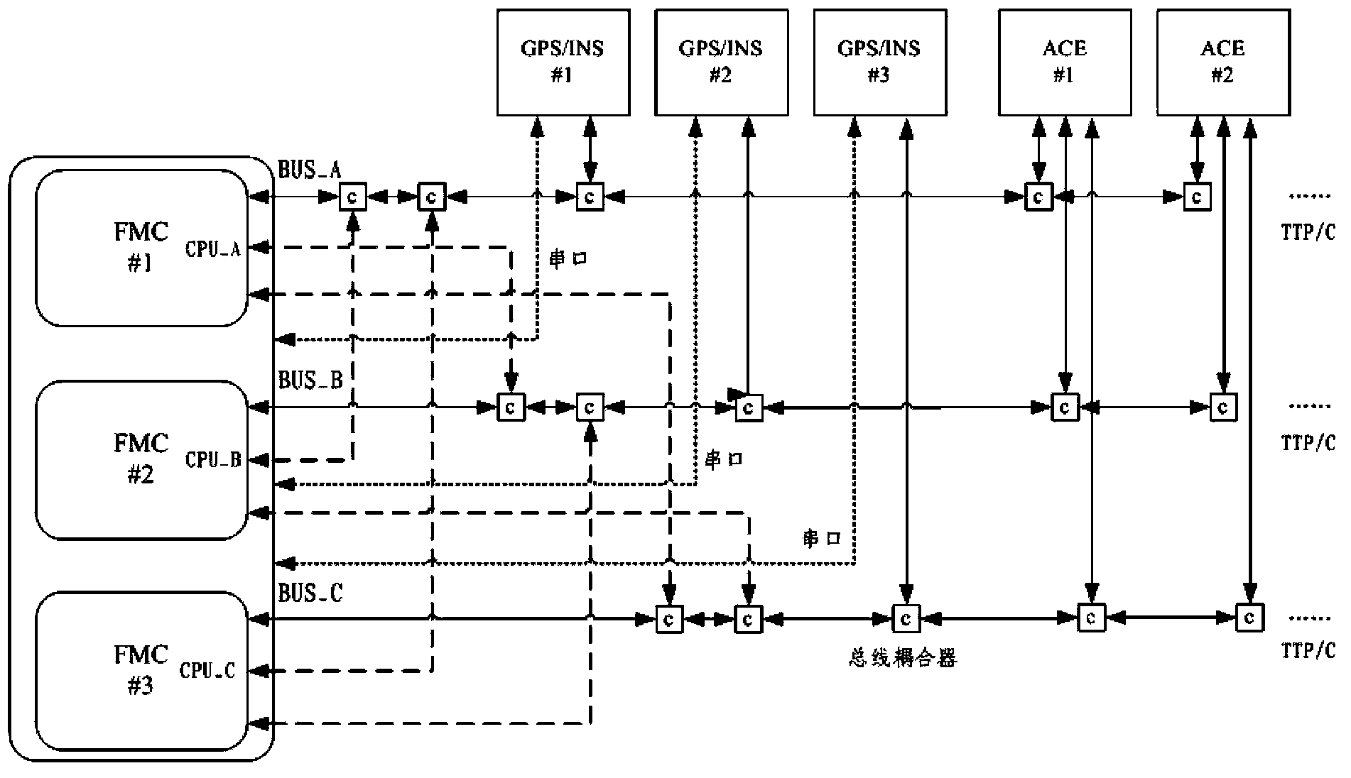
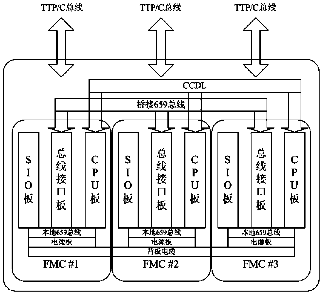
[0020] The unmanned aerial vehicle flight control system architecture based on TTP / C bus, including flight control computer, TTP / C bus and external nodes, wherein: the flight control computer includes three independent, distributed flight control calculation redundancy , each redundancy includes a complete set of CPU board, serial port board, bus interface unit and power supply module, each redundancy internally uses local 659 bus as the data bus between boards; bridge 659 bus is used between the three redundancy , the three redundant CPUs transmit data through independent CCDL modules, each redundant is connected to its external node through its own main TTP / C bus, and each redundant is also used as a node to communicate with the other two redundant connected to the main TTP / C bus.

[0021] The present invention will be described in further detail below with a specific embodiment.

[0022] The bridge 659 bus and the independent CCDL module are included between the three redu...


PUM


Abstract

The invention belongs to the field of flight control, and achieves a configuration scheme of an unmanned aerial vehicle (UAV) three redundancy flight control system (hereinafter referred to as a flight control system) architecture based on a TTP/C (Time-Triggered Protocol) bus. The architecture takes a high-performance digital three redundancy flight control computer (FMC) as a core control module, an external bus is formed by using the TTP/C bus based on time triggering, and the demanding requirements of an unmanned aerial vehicle for the flight control system are met. The architecture is beneficial for the unmanned aerial vehicle flight control system to develop in a highly reliable, real-time and open direction, and has a broad application space.

Description

technical field [0001] The invention belongs to the field of flight control and relates to the field of flight control systems. It is suitable for various control systems related to flight control such as aviation aircraft in the atmosphere and space and near-space aircraft. Background technique [0002] The flight control system is an important component of the entire aircraft. It is used to sense the movement of the body, combine automatic or artificial expectations, solve and output control commands, control the aerodynamic rudder surface of the aircraft and other cross-linking equipment, and realize the control of the aircraft as expected. Purpose. The flight control system is the "brain" and "hands and feet" of the aircraft, and it is also the key to ensuring flight safety and achieving mission goals. [0003] With the continuous development of aerospace technology and the continuous expansion of the application area, especially the cutting-edge control area, the requ...

Claims


Application Information

Patent Timeline
IPC IPC(8): G05D1/10G05B9/03
Inventor 洪锐康明杰周姝春陆鹏宋辉及鹏飞
Owner CHENGDU AIRCRAFT DESIGN INST OF AVIATION IND CORP OF CHINA
Why Eureka
Try Eureka