Automobile powertrain system rotational inertia synthetic method

A technology for automotive powertrain and moment of inertia, which is applied in special data processing applications, instruments, electrical and digital data processing, etc.

Active Publication Date: 2014-10-29
GUILIN UNIV OF ELECTRONIC TECH
View PDF2 Cites 7 Cited by
  • Summary
  • Abstract
  • Description
  • Claims
  • Application Information

AI Technical Summary

Problems solved by technology

[0008] The purpose of the embodiments of the present invention is to provide a method for synthesizing the moment of inertia of the automobile powertrain system, aimin

Method used


Image

  • Automobile powertrain system rotational inertia synthetic method
  • Automobile powertrain system rotational inertia synthetic method
  • Automobile powertrain system rotational inertia synthetic method

Examples


preparation example Construction

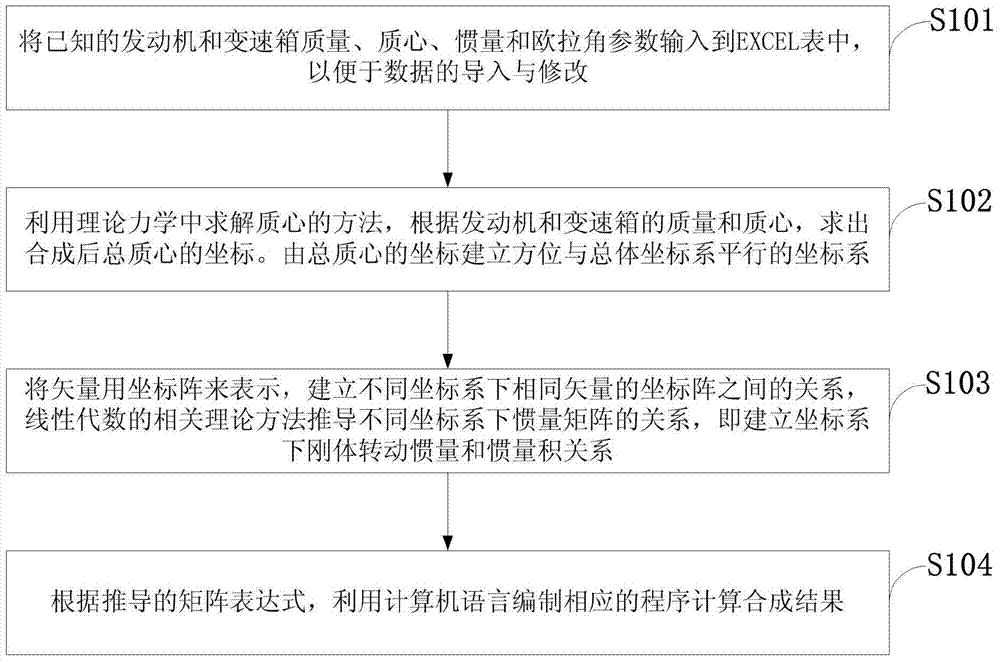
[0067] Such as figure 1 As shown, the method for synthesizing the moment of inertia of the automobile powertrain system in the embodiment of the present invention includes the following steps:

[0068] S101: input the known mass, center of mass, inertia and Euler angle parameters of the engine and gearbox into the EXCEL table, so as to facilitate data import and modification;

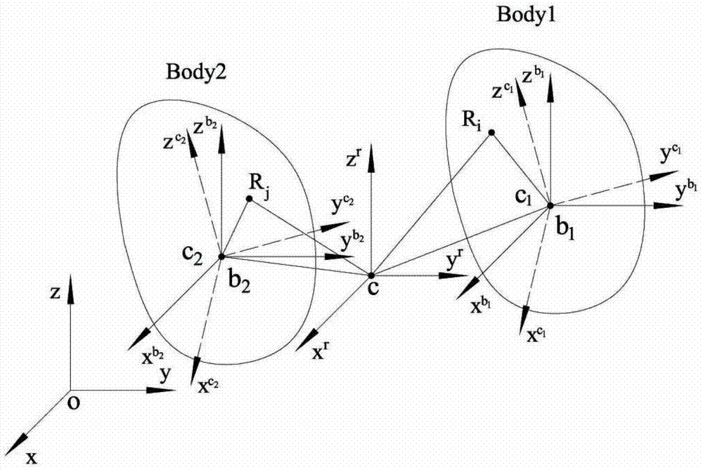
[0069] S102: Using the method of solving the center of mass in theoretical mechanics, according to the mass and center of mass of the engine and gearbox, find the coordinates of the combined total center of mass; establish a coordinate system whose orientation is parallel to the overall coordinate system from the coordinates of the total center of mass;

[0070] S103: Represent the vector with a coordinate matrix, establish the relationship between the coordinate matrix of the same vector in different coordinate systems, and use the relevant theoretical methods of linear algebra to derive the relationsh...

Embodiment 1

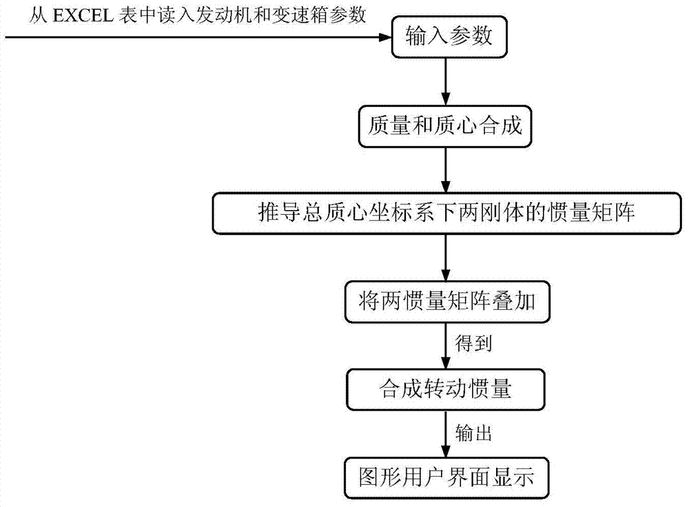
[0084] The present invention utilizes the definition of inertia, adopts matrix form derivation, has the characteristics of succinct, intuitionistic, its conclusion has extremely concise form, is easy to utilize computer language to solve, and the purpose of the present invention is to overcome the shortcoming of experimental method and large-scale commercial software synthesis method , so that it can serve the dynamic analysis and optimization of the automotive powertrain system more efficiently and conveniently;

[0085] Such as image 3 Shown, in order to realize above-mentioned purpose, the method for inertia synthesis of the present invention relates to following three basic principles: the first, utilize the definition of inertia to deduce the inertia matrix expression under different coordinate systems in matrix form, the 2nd, utilize in the linear algebra The mathematical method is to similarly transform the moment of inertia matrix to obtain the expression of the momen...


PUM


Abstract

The invention discloses an automobile powertrain system rotational inertia synthetic method. The method comprises the steps of inputting the known parameters including the mass, center of mass, inertia and eulerian angle of an engine and a gear box into an EXCEL so as to facilitate data import and correction; obtaining the coordinates of the main center of mass obtained after synthesis according to the mass and center of mass of the engine and the gearbox by means of the method for solving the center of mass in theoretical mechanics; establishing a coordinate system the orientation of which is parallel to that of a main coordinate system according to the coordinates of the main center of mass; expressing vectors with a coordinate matrix, establishing the relationship between the coordinate matrixes of the same vectors under different coordinate systems, and deducing the relationship between inertia matrixes under different coordinate systems by means of correlation theoretical methods of the linear algebra, namely establishing the relationship between rigid body rotation inertia and the product of inertia under different coordinate systems; calculating a synthesis result by means of a corresponding computer language compile program according to a deduced matrix expression. According to the method, deduction is conducted in the matrix form, briefness and visualization are achieved, the conclusion is in a quite brief form, and a solution can be obtained easily by means of the computer language.

Description

technical field [0001] The invention belongs to the technical field of automobile engineering, and in particular relates to a method for synthesizing moment of inertia of an automobile power assembly system. Background technique [0002] The moment of inertia of an object is a very important parameter in mechanical design, and its correct acquisition is the premise of statics, kinematics analysis and dynamics analysis and design of the mechanical system. [0003] In the automotive powertrain system (a system consisting of an engine, a gearbox, and suspension components), the engine and gearbox (which can be regarded as rigid bodies due to their high stiffness) generally come from different manufacturers, and the manufacturers will provide corresponding inertia parameters. (mass, center of mass and moment of inertia). However, in the automotive powertrain system, the mass, center of mass, and moment of inertia of the two objects, the engine and the gearbox, need to be synthe...

Claims


Application Information

Patent Timeline
IPC IPC(8): G06F17/50
Inventor 伍建伟刘夫云杨运泽汪沙娜甘林
Owner GUILIN UNIV OF ELECTRONIC TECH
Why Eureka
Try Eureka