Vacuum agitating barrel

A technology of vacuum mixing and mixing barrels, which is applied in the direction of mixer accessories, dissolving, mixing machines, etc., and can solve problems such as uneven mixing and poor dust removal effect

Active Publication Date: 2014-11-05
CHANGXING HUAQIANG ELECTRONICS
View PDF5 Cites 5 Cited by
  • Summary
  • Abstract
  • Description
  • Claims
  • Application Information

AI Technical Summary

Problems solved by technology

[0004] The technical problem to be solved in the present invention is to provide a vacuum mixing tank, which can solve the problems of poor dust removal and uneven mixing of traditional mixing tanks, and can quickly and labor-savingly lift the upper cover of the vacuum mixing tank to improve work efficiency

Method used


Image

  • Vacuum agitating barrel
  • Vacuum agitating barrel
  • Vacuum agitating barrel

Examples


Embodiment Construction

[0018] The specific embodiment of the present invention will be further described below in conjunction with accompanying drawing:

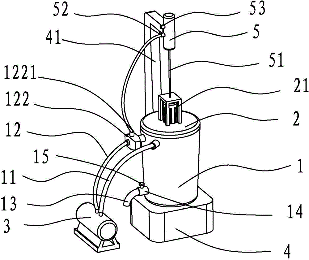
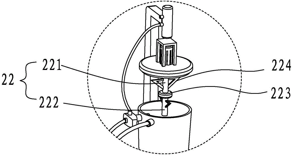
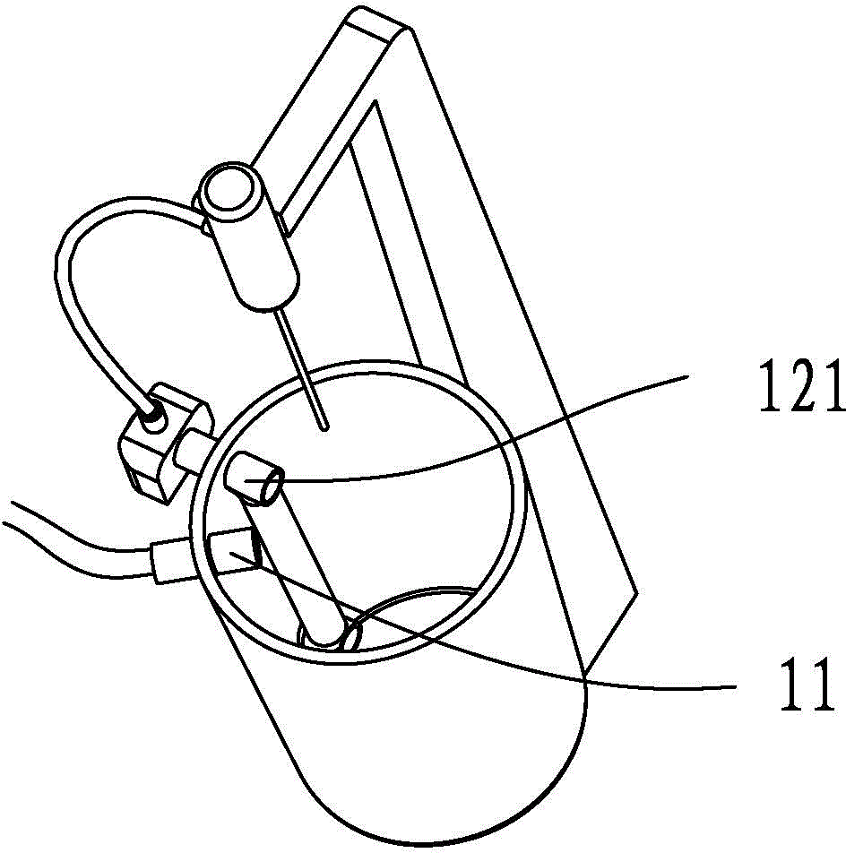
[0019] Such as Figure 1 to Figure 3 As shown, a vacuum mixing tank includes a mixing tank 1, the bottom of the mixing tank is a base, the top of the mixing tank is provided with a loam cake 2, the bottom of the loam cake is fixed with a sealing strip at the edge that is tightly closed with the mixing tank, and the top of the loam cake is provided with a There is a motor 21, a motor bracket is fixed outside the motor, a base 4 is arranged at the bottom of the mixing tank, a column 41 is fixed on the side wall of the base, and a retractable pneumatic cylinder 5 is arranged on the top of the column, and a lanyard 51 is used to connect the pneumatic cylinder and the motor bracket , the side wall of the mixing tank is provided with an air extraction pipe 11 and an air intake pipe 12, the air extraction pipe is used to remove the air in the mixing tank...


PUM


Abstract

The invention discloses a vacuum agitating barrel. The vacuum agitating barrel comprises an agitating barrel, wherein an upper cover is arranged on the agitating barrel; a motor is arranged at the top of the upper cover; an agitating rod is arranged at the bottom of the upper cover; an exhausting pipe and an air inlet pipe are arranged on the side wall of the agitating barrel; the exhausting pipe and the air inlet pipe are connected with an air pump; a pneumatic cylinder for lifting is arranged above the upper cover; the pneumatic cylinder is connected with the air inlet pipe; the agitating rod comprises an upper rod and a lower rod; a shaft coupler is arranged between the upper rod and the lower rod; the shaft coupler is internally provided with a steering device for setting the rotation directions of the upper rod and the lower rod to be opposite; a discharge hole is formed in the bottom of the agitating barrel; a pneumatic valve is arranged at the discharge hole; a two-way pipe is arranged in the agitating barrel for the air inlet pipe; a channel is communicated with a cavity above the agitating barrel and the other channel is communicated with the pneumatic valve; an anti-blocking touch switch is arranged on the pneumatic valve. According to the vacuum agitating barrel, the problems of a traditional agitating barrel that the dust removing effect is not good and the agitation is not uniform can be solved; the upper cover of the vacuum agitating barrel can be rapidly and easily lifted so that the working efficiency is improved.

Description

technical field [0001] The invention relates to a vacuum mixing tank. Background technique [0002] Mixers are often used in modern food or chemical industries, and these industries have high requirements for the purity of materials when mixing, and it is required to minimize the mixing of impurities during mixing, so mixing in ordinary environments can no longer meet the requirements of these industries. , there are also some vacuum mixers on the market now, which allow the materials to be in a vacuum environment during mixing to prevent dust in the air from entering the mixing materials, but the traditional vacuum mixers have problems of uneven mixing and insufficient dust removal, especially after mixing. When the upper cover is opened and the material is poured, the material will still come into contact with the dust in the air. Compared with stirring the material directly in the air, although the contact time is shortened, the dust removal effect is still not good. [...

Claims


Application Information

Patent Timeline
IPC IPC(8): B01F13/06B01F15/00
Inventor 刘金宝柯云李超超李梅郑美吴军
Owner CHANGXING HUAQIANG ELECTRONICS
Why Eureka
Try Eureka