Hot melt special machine and hot melt method using the hot melt special machine

A hot-melt and special machine technology, applied in the field of hot-melt special machine and auto parts hot-melt equipment, can solve the problems of flat riveting forming effect, easy damage to products, bad riveting points, etc., to ensure the forming effect, eliminate potential safety hazards, Guarantee the effect of riveting force

Active Publication Date: 2014-11-05
JIAXING XINYUAN PRECISION MOLD TECH
View PDF4 Cites 10 Cited by
  • Summary
  • Abstract
  • Description
  • Claims
  • Application Information

AI Technical Summary

Problems solved by technology

[0002] The hot-melt special machine is to complete the hot-melt riveting problem between plastic parts, such as a kind of hot-melt machine disclosed in Chinese patent document announcement number: CN103057118A, including a fuselage, which is provided with a product positioning platform and a hot-melt joint. device, the bottom of the hot-melt device is provided with a number of hot-melt heads facing the product positioning platform, and a power mechanism is provided on the body, and the power mechanism can drive the hot-melt device relative to the product positioning platform By moving up and down, it can be seen that although the hot-melt machine can complete half of the hot-melt process steps, since the hot-melt machine has no buffer during hot-melt, the riveting forming effect will be very flat, and bad riveting points are easy to appear, which is easy to hurt The product does not produce defective products, which are prone to bad riveting points, and some points need to be repaired manually. At the same time, there is no air cut-off barrier, and the heating element and the fuselage can be electrically connected, which poses a safety hazard

Method used


Image

  • Hot melt special machine and hot melt method using the hot melt special machine
  • Hot melt special machine and hot melt method using the hot melt special machine
  • Hot melt special machine and hot melt method using the hot melt special machine

Examples


Embodiment Construction

[0027] The following are specific embodiments of the present invention and in conjunction with the accompanying drawings, the technical solutions of the present invention are further described, but the present invention is not limited to these embodiments.

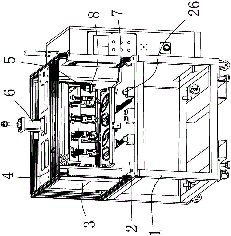
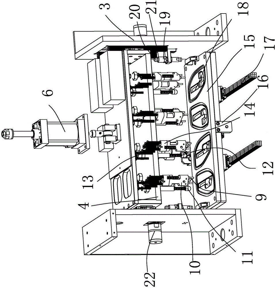
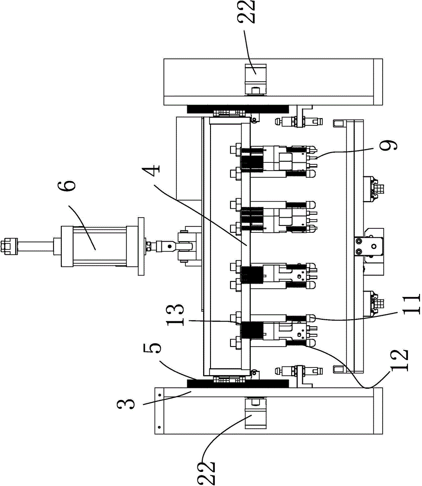
[0028] In the figure, frame 1; product table 2; mounting frame 3; upper mold fixing plate 4; up and down moving guide rail 5; up and down moving cylinder 6; Hot-melt fixing part 10; pre-compression rod 11; primary buffer part 12; secondary buffer part 13; insulation block 14; lower mold placing platen 15; front and rear movement cylinder 16; front and rear movement guide rail 17; product placement position 18; Slowing down limit block 19; slowing down head 20; slowing down spring 21; air cut-off blocking mechanism 22; pre-blocking sleeve piece 23; pre-blocking spring 24;

[0029] Such as figure 1 , figure 2 as well as image 3 As shown, this hot-melt special machine includes a frame 1 and a product workbench 2 arranged...


PUM


Abstract

The invention belongs to the technical field of automobile part hot melt equipment, and provides a hot melt special machine and a hot melt method using the hot melt special machine. The hot melt special machine comprises a frame and a product work bench arranged on the frame; an installation rack, an upper mould fixing plate, an up-down movement guide rail, and an up-down movement cylinder are arranged on the product work bench, the bottom surface of the product work bench is provided with a lower mould storage mechanism, the lower part of the upper mould fixing plate is provided with a mechanism for heating and melting rivets, and the mechanism is opposite to the lower mould storage mechanism and is provided with a secondary buffer mechanism. The hot melt special machine has the advantages that a secondary buffer mechanism is added to guarantee the moulding effect and the rivet force so as to reduce the generation rate of substandard products. Furthermore, an electric and heat insulation block is designed to electrically disconnect the heating body of the hot melt head and the frame so as to eliminate the safety hazard. A gas-cutting baffle mechanism is added to guarantee the safety during sudden interruption of gas supply.

Description

technical field [0001] The invention belongs to the technical field of hot-melt equipment for auto parts, and relates to a special hot-melt machine and a hot-melt method using the special hot-melt machine. Background technique [0002] The hot-melt special machine is to complete the hot-melt riveting problem between plastic parts, such as a kind of hot-melt machine disclosed in Chinese patent document announcement number: CN103057118A, including a fuselage, which is provided with a product positioning platform and a hot-melt joint. device, the bottom of the hot-melt device is provided with a number of hot-melt heads facing the product positioning platform, and a power mechanism is provided on the body, and the power mechanism can drive the hot-melt device relative to the product positioning platform By moving up and down, it can be seen that although the hot-melt machine can complete half of the hot-melt process steps, since the hot-melt machine has no buffer during hot-melt...

Claims


Application Information

Patent Timeline
Patent Type & Authority Applications(China)
IPC IPC(8): B29C65/18
Inventor 黄敏
Owner JIAXING XINYUAN PRECISION MOLD TECH
Why Eureka
Try Eureka