Auxiliary coupling device for transitional coupler

A transition coupler and coupling technology, which is applied in transportation and packaging, railway car body parts, railway vehicle coupling accessories, etc., can solve the problems of non-rotation, poor flexibility and versatility, etc., to extend the maintenance cycle and improve the connection Linking the Effects of Flexibility and Versatility

Active Publication Date: 2016-06-29
CRRC QINGDAO SIFANG ROLLING STOCK RES INST +1
View PDF6 Cites 1 Cited by
  • Summary
  • Abstract
  • Description
  • Claims
  • Application Information

AI Technical Summary

Problems solved by technology

[0003] In the process of field application, especially the technical configuration adopted by domestic EMU trains is different, and the size of the connecting surface of the front coupler of each model is different, so the use of the current transitional coupler has great limitations: the existing transitional coupler is only equipped with a single auxiliary The connecting device and the auxiliary connecting device are fixed and non-rotatable. They are only suitable for the front-end coupler equipped with a single vehicle type. When in use, they can only be manually connected to the close-fitting coupler, and then connected to the traction coupler of the locomotive by impact. Flexible less versatile

Method used


Image

  • Auxiliary coupling device for transitional coupler
  • Auxiliary coupling device for transitional coupler
  • Auxiliary coupling device for transitional coupler

Examples


Embodiment 1

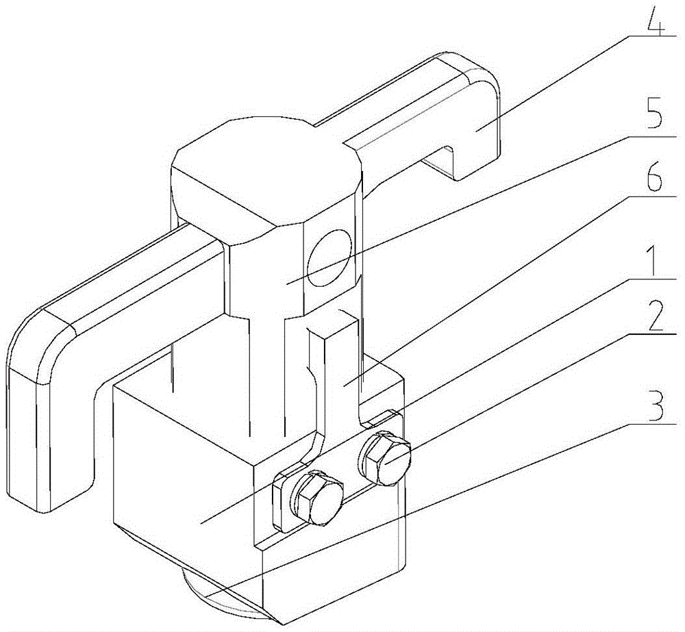
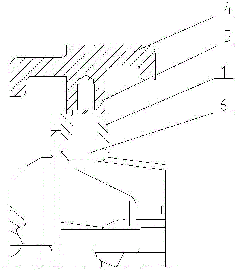
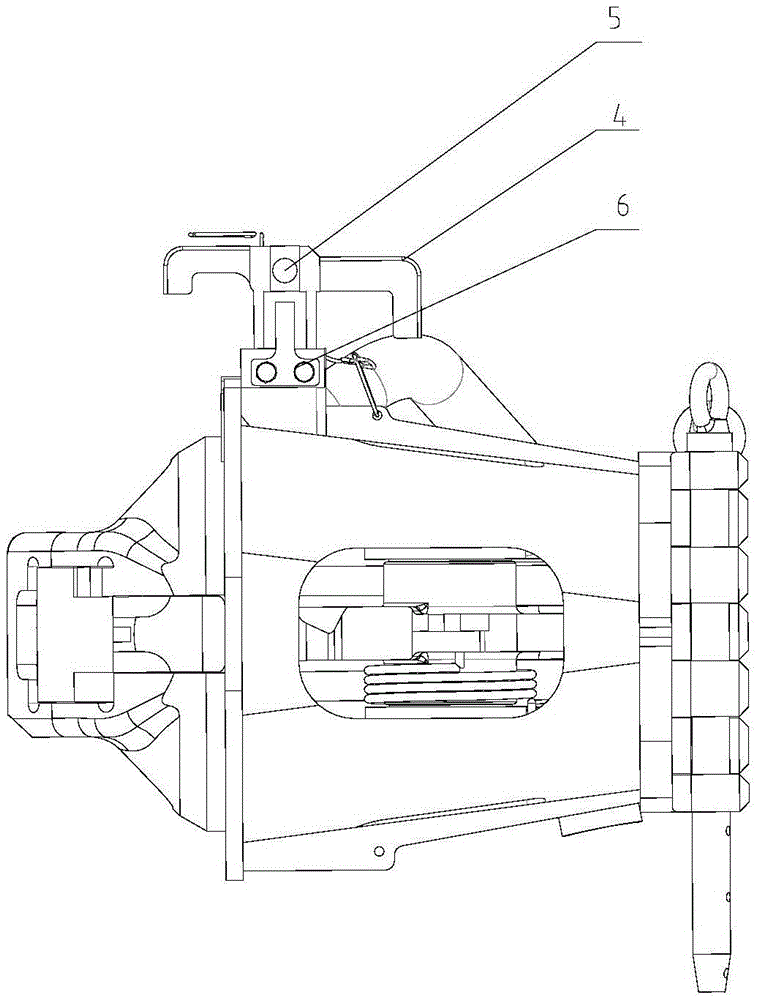
[0025] see figure 1 and figure 2 , an auxiliary coupling device for a transitional coupler, used for coupling the front-end coupler of a vehicle, the device includes an auxiliary hook, a support 1, a locking device, a fastener 2 and a pivot pin 3, and the auxiliary hook includes a hook facing downwards 4 and the hook connecting column 5, and the hook 4 is horizontally arranged on the side of the hook connecting column 5, the upper end of the hook connecting column 5 is integrally formed with the hook 4, the bottom end of the hook connecting column 5 is connected with the rotating shaft pin 3, and the hook connecting column 5 can be Rotate synchronously with the pivot pin 3, when the position of the hook 4 and the front coupler are not uniform, the pivot pin 3 can be rotated to drive the auxiliary hook to rotate to the coupler coupling angle; when the auxiliary coupling function is not needed, the pivot pin 3 can be rotated to drive the auxiliary hook Rotate to an appropriate...

Embodiment 2

[0032] The structure and composition of the auxiliary connecting device of embodiment 2 are basically the same as that of embodiment 1, and the difference technical feature is that there is one hook 4 in total, and the hook 4 is arranged at the upper end of the side of the hook connecting column 5 .

Embodiment 3

[0034] The structure and composition of the auxiliary connecting device of embodiment 3 and the auxiliary connecting device of embodiment 1 are basically the same, and the difference technical features are: as Figure 5 As shown, there are 2 hooks 4 in total, and the 2 hooks are arranged at the upper end of the side of the hook connecting column 5 at intervals of 180°.


PUM


Abstract

The invention relates to an auxiliary coupling device for a transition coupler, which is used for coupling the front-end coupler of a vehicle. Column, the upper end of the hook connecting column is integrally formed with the hook, the bottom end of the hook connecting column is connected with the shaft pin; the middle part of the support is provided with a counterbore, the hook connecting column passes through the counterbore longitudinally, and the hook connecting column and the described The rotating shaft pin rotates synchronously under the support of the counterbore. The rotating rotating shaft pin can drive the auxiliary hook to rotate to the coupling hook angle, and the rotating shaft pin can also rotate the rotating shaft pin to drive the auxiliary hook to rotate to an appropriate angle to ensure that any hook does not protrude from the connecting surface. Affecting the normal operation of the automatic coupling, the manual coupling with the front coupler can be realized, and by turning the auxiliary coupling to a different position, it can be connected to the close coupling or the locomotive coupling first, which improves the on-site shunting and reconnection. Flexibility and versatility of work.

Description

technical field [0001] The invention relates to a vehicle coupler connecting device, in particular to an auxiliary connecting device for a transitional coupler. Background technique [0002] The transition coupler is usually used to connect the transported vehicle and the power locomotive, and is an important device for vehicle shunting operations, train return and rescue. In the field of high-speed trains, intercity EMUs and urban rail vehicles, the transition coupler of the close-connected automatic coupler-buffer device is very common. [0003] In the process of field application, especially the technical configuration adopted by domestic EMU trains is different, and the size of the connecting surface of the front coupler of each model is different, so the use of the current transitional coupler has great limitations: the existing transitional coupler is only equipped with a single auxiliary The connecting device and the auxiliary connecting device are fixed and non-rota...

Claims


Application Information

Patent Timeline
Patent Type & Authority Patents(China)
IPC IPC(8): B61G7/00
Inventor 刘辉段书华刘世郑伟
Owner CRRC QINGDAO SIFANG ROLLING STOCK RES INST
Why Eureka
Try Eureka