
Rotor wing control mechanism for coaxial helicopter

A coaxial helicopter and control mechanism technology, which is applied in the directions of rotorcraft, motor vehicles, aircraft, etc., can solve the problems of difficulty in reducing the drag of the propeller hub, difficulty in reducing the resistance of the rotor system, and large windward area, so that the rotor is responsive to manipulation. , the rules of airflow change, the effect of small windward area

Active Publication Date: 2014-11-05
CHINA ACAD OF AEROSPACE AERODYNAMICS
View PDF7 Cites 20 Cited by
  • Summary
  • Abstract
  • Description
  • Claims
  • Application Information

AI Technical Summary

Problems solved by technology

According to the current technology, the rotor control mechanism of the coaxial helicopter is outside the rotor shaft, and the windward area is large, and it is difficult to take drag reduction measures for the hub, and it is difficult to reduce the resistance of the rotor system

Method used


Image

  • Rotor wing control mechanism for coaxial helicopter
  • Rotor wing control mechanism for coaxial helicopter
  • Rotor wing control mechanism for coaxial helicopter

Examples


Embodiment Construction

[0034] The present invention will be further described in detail below in conjunction with the accompanying drawings and specific embodiments.

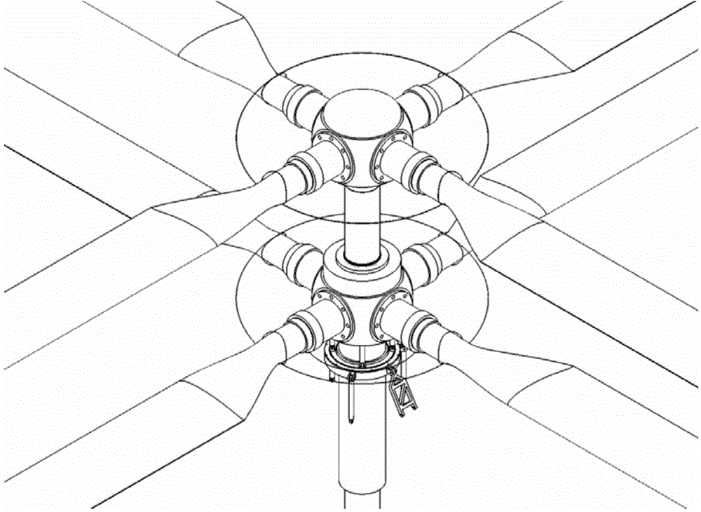
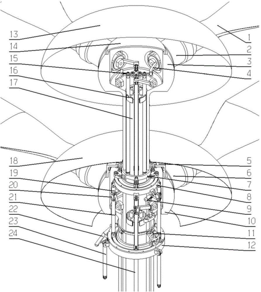
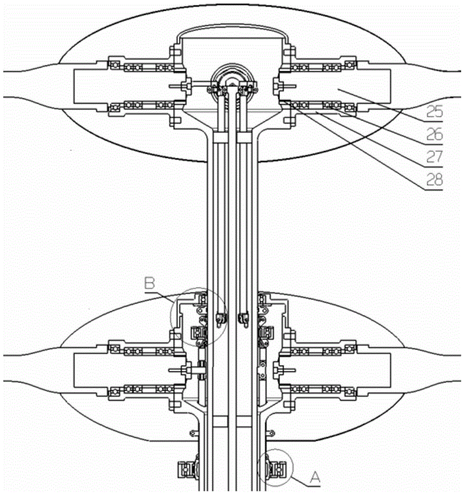
[0035] Such as Figure 1a , Figure 1b , Figure 1c Shown: The upper and lower rotor blades of the coaxial helicopter are all four. The corresponding operating mechanism comprises outer shaft 10, inner shaft 3, inner and outer shaft support base 5, outer automatic tilter 12, inner automatic tilter 8, intermediate ring 7, and three pull-down rods 23, four middle pull-rods 21, four small Pull rod 19, four lower cross bars 39, four upper tie rods 17, four upper cross bars 15, a long tie rod 24, upper limit device 16, lower limit device, lower rotor hub 6, upper rotor hub 2, and upper The upper rotor pitch variable rocker 4 connected to the inner end of the rotor hub, the lower rotor pitch variable rocker 20 connected to the inner end of the lower rotor hub, the first torque arm 22, the second torque arm 11, and the third torque arm 9....


PUM


Abstract

The invention discloses a rotor wing control mechanism for a coaxial helicopter. The mechanism comprises an outer shaft, an inner shaft, an inner and outer shaft supporting base, an outer automatic tilting device, an inner automatic tilting device, a middle ring, a third connecting device, a plurality of lower pull rods, a plurality of first connecting devices, a plurality of lower horizontal rods, a plurality of second connecting devices, a plurality of lower rotor wing propeller hubs which are mounted on the propeller hub head of the outer shaft, a plurality of upper rotor wing propeller hubs which are mounted on the propeller hub head of the inner shaft, a plurality of upper rotor wing variable-pitch rocker arms which are connected with the inner ends of the upper rotor wing propeller hubs, and a plurality of lower rotor wing variable-pitch rocker arms which are connected with the inner ends of the lower rotor wing propeller hubs. Lower rotor wing control mechanisms are distributed into a helicopter body fairing and a lower rotor wing fairing, and upper rotor wing control mechanisms are distributed in a rotor wing shaft. Through the adoption of the mutual matching and control of the lower pull rods and long pull rods, the synchronous control of the total distance, the differential action control of the total distance, and the control of the cyclic variable pitch for an upper rotor wing and a lower rotor wing can be realized through all parts.

Description

technical field [0001] The invention relates to the technical field of aircraft design, in particular to a rotor control mechanism of a coaxial helicopter. Background technique [0002] The control mechanism is an important part of the helicopter. The driver must control the flight of the helicopter through the control system to maintain or change the balance of the helicopter. A coaxial helicopter is a rotor-type aircraft with two upper and lower rotors that counter-rotate around a coaxial axis. Since the coaxial helicopter has two upper and lower rotors, its rotor control system is more complicated than that of conventional helicopters. [0003] Generally, the hub resistance of a single-rotor helicopter accounts for 20% to 30% of the total waste resistance of the helicopter, and the coaxial helicopter has two hubs, and the hub resistance accounts for more than 50% of the total waste resistance. With the increase of flight speed, the airframe resistance can be further red...

Claims


Application Information

Patent Timeline
Patent Type & Authority Applications(China)
IPC IPC(8): B64C27/10B64C27/12
Inventor 吴伟伟马存旺张凯汪洋
Owner CHINA ACAD OF AEROSPACE AERODYNAMICS
Learn More