Laser cutting mechanism used for clothes cutting equipment

A laser machine base and laser technology, applied in the field of clothing machinery, can solve the problems of slow smoke exhaust speed, fixed area, poor heat dissipation effect, etc., and achieve the effects of high automation, fast smoke exhaust speed and high production efficiency

Inactive Publication Date: 2014-11-05
佛山市顺德区爱斯达科技研发有限公司
View PDF6 Cites 4 Cited by
  • Summary
  • Abstract
  • Description
  • Claims
  • Application Information

AI Technical Summary

Problems solved by technology

However, the existing laser cutting machines still have the following deficiencies: (1) The working table of the existing laser cutting machine is basically a platform. Since the laser cutting adopts the principle of fusion cutting, the working table of the laser cutting machine is easy to cause cloth Adhesion phenomenon, and the adhesion of the fabric on the platform will also affect the quality of the fabric to be c

Method used


Image

  • Laser cutting mechanism used for clothes cutting equipment

Examples


Embodiment 1

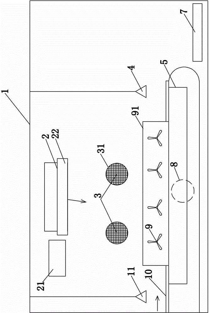
[0016] Example 1, such as figure 1 As shown, a kind of clothing cutting equipment comprises laser cutting mechanism, and this laser cutting mechanism comprises studio 1, laser generator 2 and conveying network chain 10, and the top and bottom of described conveying network chain 10 are respectively provided with smoking port 3 and The air exhaust port 8, the corresponding smoke outlet 3 on the conveying network chain 10 is provided with an air blower 9, the laser frame 22 is arranged on the top of the conveying network chain 10, the laser generator 2 is installed on the laser frame 22, the The feed end of conveying network chain 10 is provided with tailing sensor 11, and the discharging end of described conveying network chain 10 is provided with stop sensor 4, and the below of the discharging end of described conveying network chain 10 is provided with the conveyer belt that is used for picking up and sending cloth. 7. The smoke outlet 3 and the air outlet 8 are connected in...


PUM


Abstract

The invention relates to the technical field of clothes machines, in particular to a laser cutting mechanism used for clothes cutting equipment. The laser cutting mechanism used for the clothes cutting equipment comprises a working chamber, a laser generator, a laser base and a conveying network chain. A smoke pumping port and an air pumping port are formed in the upper portion and the lower portion of the conveying network chain respectively and are located on the same side of the conveying network chain. The position, corresponding to the smoke pumping port, of the other side of the conveying network chain is provided with an air supply draught fan. The laser base is arranged above the conveying network chain. The laser generator is installed on the laser base. A tailing sensor is arranged at the feeding end of the conveying network chain, and a stopping sensor is arranged at the discharging end of the conveying network chain. A conveyor belt used for receiving and conveying cloth is arranged below the discharging end of the conveying network chain. As the smoke pumping port and the air pumping port are formed in the upper portion and the lower portion of the conveying network chain respectively, the smoke discharge speed is high, the cooling effect is better, cloth adhesion is avoided, and it is ensured that cloth is sucked and tensioned on the conveying network chain.

Description

technical field [0001] The invention relates to the technical field of clothing machinery, in particular to a laser cutting mechanism for clothing cutting equipment. Background technique [0002] Existing laser cutting equipment is widely used in the clothing and bag industries, for cutting textiles, such as laser cutting machines. But the existing laser cutting machine still has the following disadvantages: (1) The worktable of the existing laser cutting machine is basically a platform. Adhesion phenomenon, and the adhesion of the fabric on the platform will also affect the quality of the fabric to be cut later. (2) The working table area of ​​the existing laser cutting machine is fixed, and it is impossible to carry out large-format work, which restricts the popularization and use of the laser cutting machine. (3) The smoke exhaust speed of the existing laser cutting machine is slow, and the heat dissipation effect is poor, resulting in the edge of the cut fabric being y...

Claims


Application Information

Patent Timeline
IPC IPC(8): B65H35/06B65H43/00
Inventor 樊友斌
Owner 佛山市顺德区爱斯达科技研发有限公司
Why Eureka
Try Eureka