Cylindrical hydraulic tappet

A hydraulic tappet and columnar technology, which is applied in the direction of engine components, machines/engines, mechanical equipment, etc., can solve problems such as valve clearance cannot be eliminated, complex processing technology, increased noise, etc., to reduce the risk of air mixing into high-pressure chambers, The effect of simple molding process and high processing efficiency

Active Publication Date: 2014-11-05
HANGZHOU XZB TECH
View PDF11 Cites 10 Cited by
  • Summary
  • Abstract
  • Description
  • Claims
  • Application Information

AI Technical Summary

Benefits of technology

This patented method for manufacturizing plunges involves combining different materials together during injection molded processes. By integrating multiple parts like the fuel tank or cylinder head, these components become stronger without requiring extra weight compared to traditional methods such as casting. Additionally, the use of lubrication coil channels allows for better coolability while maintaining good oil retention characteristics. Overall, this new design improves heat dissipation performance and reduces damage from excessive internal combustion pressings.

Problems solved by technology

This patented technical problem addressed in this patents relating to the use of hydrostatic thrust bearings (HBF), specifically those called ballistic or rolling type Hydrojet Mechanisms (SHM). These mechanisms have several benefits such as improved performance over traditional engines due to their ability to adjust without stopping power supply and reduce vibration levels compared to older designs. However they also generate more waste products like lubricant residue and gasoline combustion gases. Additionally, some components become worn faster even before reaching peak operating hours, causing issues like decreased durability and acceleration felt down upon operation.

Method used


Image

  • Cylindrical hydraulic tappet
  • Cylindrical hydraulic tappet
  • Cylindrical hydraulic tappet

Examples


Embodiment 1

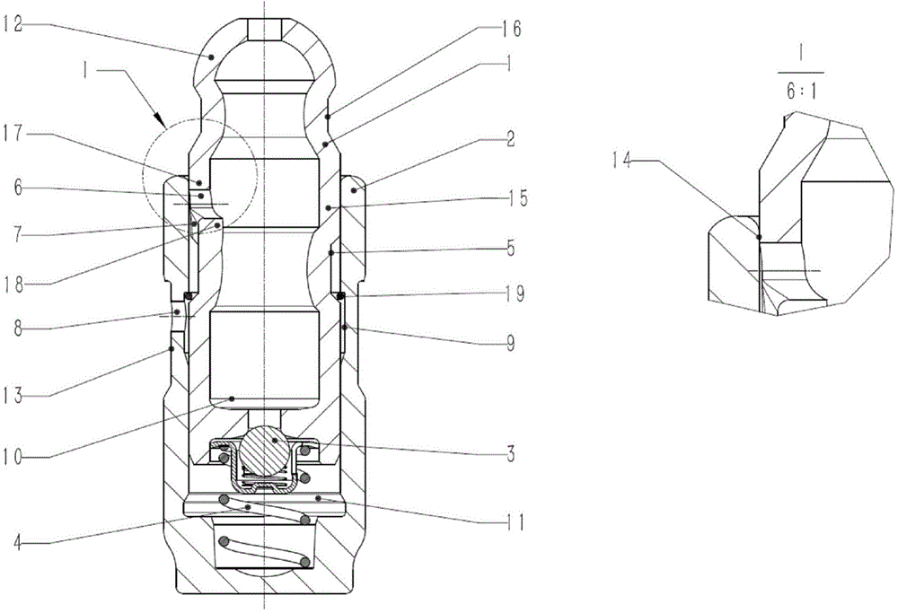
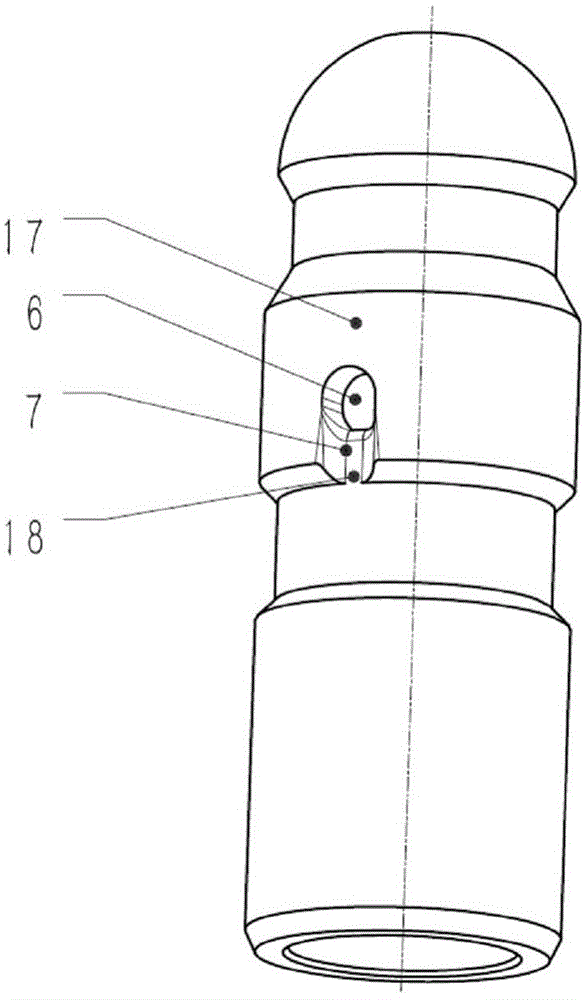
[0056] like figure 1 As shown, the columnar hydraulic tappet used in the engine valve train, the hydraulic tappet has a pot-shaped housing (2), and an axially slidable plunger is arranged in the inner cavity of the housing (2) (1). There is a high-pressure chamber (11) between the lower end surface of the plunger (1) and the housing (2), and the high-pressure chamber (11) can be closed by a one-way valve (3) located at the lower end of the plunger (1). The high-pressure chamber (11) has a return spring (4) connecting the plunger (1) and the casing (2). On the outer diameter of the housing (2) there is an outer ring groove (13) for the circulation of the hydraulic medium, and on the radial inner side of the housing (2) there is an inner ring groove (9) for the circulation of the hydraulic medium. One or more oil holes (8) for hydraulic medium circulation are provided between the inner ring groove (9) of the casing and the outer ring groove (13) of the casing. The outer diame...

Embodiment 2

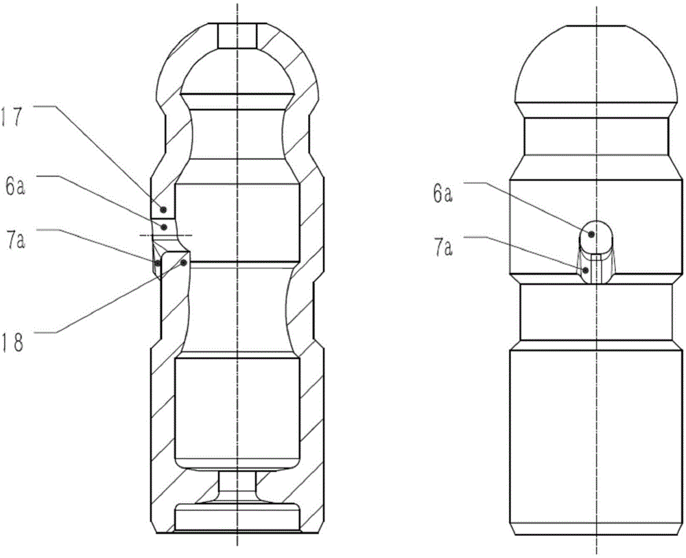
[0061] like Figure 4 As shown, the difference from Example 1 is that the side walls at both ends of the oil groove (7b) are not parallel, and are in the shape of outward expansion, as shown in the figure, which increases the flow area and facilitates the smooth flow of oil into the plunger Oil inlet hole (6b).

Embodiment 3

[0063] like Figure 5 As shown, the difference from Example 1 is that the shape of the plunger oil inlet hole (6c) is a circular hole, the shape of the oil groove (7c) is a concentric semicircle with a diameter larger than that of the plunger oil inlet hole (6c) at the top, and the shape of the bottom is The sidewalls at both ends are tangent to the concentric semicircle, and the sidewalls at both ends are parallel or outwardly expanded; the circular sidewall of the oil groove (7c) does not coincide with the hole wall of the oil inlet hole (6c), and the oil inlet hole (6c) There is a concave tapered surface (20) on the outside, which prevents the air from being brought in when the oil enters the oil inlet hole (6c) of the plunger.


PUM


Abstract

The invention belongs to the technical field of manufacturing of engine accessory. The cylindrical hydraulic tappet comprises a casing. A plunger piston capable of moving axially relative to the casing is mounted in an inner cavity of the casing correspondingly. A first ring groove is formed below the head of the plunger piston, a second ring groove is formed in the middle of the plunger piston, a plunger piston center wall is defined between the first ring groove and the second ring groove, and the second ring groove is a recessed wide ring groove. The cylindrical hydraulic tappet is characterized in that at least one oil inlet which is communicated with the second ring groove is formed in the plunger piston center wall, and a sealing strip which is matched with the inner cavity of the casing to cut off flowing of a hydraulic medium is reserved on the upper portion of the plunger piston center wall. The oil inlets of the plunger piston are formed in position relatively higher than a check valve so that oil storage capacity of an oil storage cavity of the plunger piston is increased; during cold start of an engine, sufficient hydraulic medium can be resupplied rapidly to enter a high-pressure cavity in the check valve, the time for the hydraulic tappet to reset to a normal work height from a compression height is shortened, the valve clearance is eliminated quickly, the noise reduction time during the cold start of a valve distributing mechanism is shortened while abrasion of related parts is reduced.

Description


Claims


Application Information

Patent Timeline
Owner HANGZHOU XZB TECH
Why Eureka
Try Eureka