Fluid pipeline leak detection and positioning method

A technology of leak detection and positioning method, which is applied in the direction of fluid tightness test, pipeline system, measuring device, etc., and can solve problems such as large amount of calculation, increased problem complexity, and decreased positioning accuracy

Active Publication Date: 2014-11-05
CHONGQING UNIV
View PDF6 Cites 19 Cited by
  • Summary
  • Abstract
  • Description
  • Claims
  • Application Information

AI Technical Summary

Problems solved by technology

[0003] The correlation location method is a pipeline leakage location method based on delay estimation. It is not difficult to see from its processing that the implementation of this method is based on the known propagation velocity of the acoustic vibration signal in the pipeline. However, in engineering In practice, due to the influence of pipeline material, size, burial conditions, environmental changes and other factors, the propagation speed of the acoustic vibration signal in different pipelines is different, and even in different sections of the same pipeline, the propagation speed of the acoustic vibration signal There are also differences, which undoubtedly increase the complexity of the problem. In order to simplify this problem in the prior art, the theoretical value or estimated value of sound velocity is usually used instead of the actual sound velocity, which is quite different from the actual sound velocity, and there is a large principle error , and the positioning accuracy brought by the error will drop sharply with the increase of the pipeline length, making it difficult to apply the correlation positioning method to the monitoring of large-length pipelines
[0004] Aiming at the aforementioned problems, those skilled in the art have also conducted research and proposed some alternatives, such as the blind system identification method proposed by Yang Jin et al. to estimate the absolute time of leakage acoustic signal transmission in the pipeline. When the sound velocity of the signal is unknown, the leakage location of the fluid pipeline can be calculated, and the actual sound velocity value of the pipeline can be calculated. However, the algorithm of this method is complex, the amount of calculation is large, and the collected signal should have a high signal-to-noise ratio for analysis. Its applicable detection distance is relatively short (J.Yang, Y.Wen and P.Li, Leak location using blind system identification in water distribution pipelines, Journal of Sound and Vibration 310(2008) 134-148.J.Yang, Y .Wen and P.Li, The genetic-algorithm-enhanced blind system identification for water distribution pipeline leak detection, Measurement Science and Technology 18(2007) 2178-2184.)

Method used


Image

  • Fluid pipeline leak detection and positioning method
  • Fluid pipeline leak detection and positioning method
  • Fluid pipeline leak detection and positioning method

Examples


Embodiment Construction

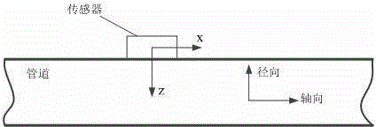
[0069] A method for detecting and locating fluid pipeline leaks, including a pipeline under test. The innovation is that at least two sensing devices are arranged on the pipeline under test, and there is a certain distance between the two sensing devices. collection point, the sensing device can simultaneously sense pipeline acoustic vibrations in two directions, the two directions being the pipeline axial direction and the pipeline radial direction; when there is leakage on the measured pipeline between the two collection points When the leak point is detected, locate the leak point according to the following methods:

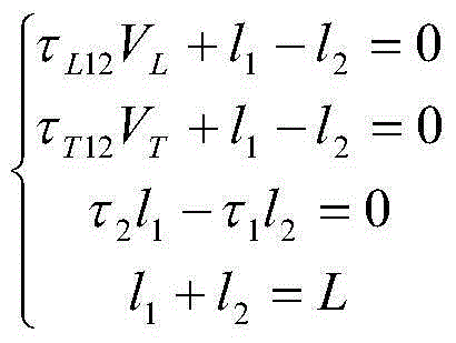
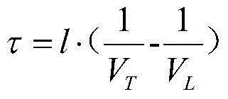
[0070] Let the two collection points be collection point 1 and collection point 2 respectively, the distance between the two collection points is denoted as L, and the distance between collection point 1 and the leakage point is denoted as l 1 , the distance between collection point 2 and leakage point is denoted as l 2 , the propagation velocity of the longi...


PUM


Abstract

The invention discloses a fluid pipeline leak detection and positioning method. A measured pipeline is included in the method. The method is characterized in that at least two sensing devices are arranged on the measured pipeline, the two sensing devices are spaced by a certain distance, the positions where the sensing devices are located form collection points, the sensing devices can sense the acoustic vibration of the pipeline in two directions simultaneously, and the two directions are the axial direction and the radial direction of the pipeline respectively; when a leak point exists in the portion, between the two collection points, of the measured pipeline, the leak point is positioned according to the following formula (see the instructions). The fluid pipeline leak detection and positioning method has the advantages that the positioning accuracy is good, the wave velocity of acoustic vibration of the pipeline does not need to be known, the processing complexity is low, and the longitudinal wave sound velocity and transverse wave sound velocity of the pipeline can be measured actually.

Description

technical field [0001] The invention relates to a pipeline leakage positioning technology, in particular to a fluid pipeline leakage detection and positioning method. Background technique [0002] In the detection and location of fluid pipeline leaks, the correlation peak location method is the most commonly used method. The specific operation of the correlation peak location method is: set several collection points on the pipeline to be tested, and each collection point is equipped with an acoustic sensor or a vibration sensor. Sensors, during the detection process, cross-correlation processing is performed on the output signals of two adjacent sensors. If there are obvious correlation peaks in the output signals of the two sensors, it indicates that there is a leak point on the pipeline between the collection points where the two sensors are located. The location of the correlation peak is the time delay from the propagation of the acoustic vibration signal at the leak poi...

Claims


Application Information

Patent Timeline
Patent Type & Authority Applications(China)
IPC IPC(8): F17D5/02
CPCG01M3/243F17D5/06
Inventor 李平文玉梅李帅永文静邱景杨进朱永王宁
Owner CHONGQING UNIV
Why Eureka
Try Eureka