gas boiler burner

A gas boiler and burner technology, applied in the direction of burners, gas fuel burners, combustion methods, etc., can solve the problems of high flame port temperature, short service life, insufficient combustion, etc., and achieve high combustion calorific value and high temperature , The effect of stable and sufficient combustion

Active Publication Date: 2017-01-18
NINGBO DUOBEI MACHINERY IND
View PDF9 Cites 3 Cited by
  • Summary
  • Abstract
  • Description
  • Claims
  • Application Information

AI Technical Summary

Problems solved by technology

The existing technology has the following defects and deficiencies due to the structural setting: 1. Because the gas is not fully mixed with the air, the combustion is insufficient, resulting in waste of resources; 2. The temperature around the flame port is high, and because there is no cooling system, after long-term use, Easy to burn out, resulting in short service life
Therefore, there is a large room for improvement in the current technology

Method used


Image

  • gas boiler burner
  • gas boiler burner
  • gas boiler burner

Examples


Embodiment 1

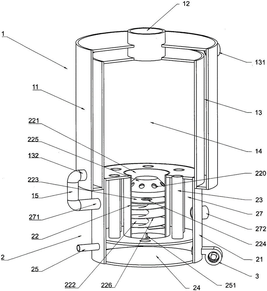
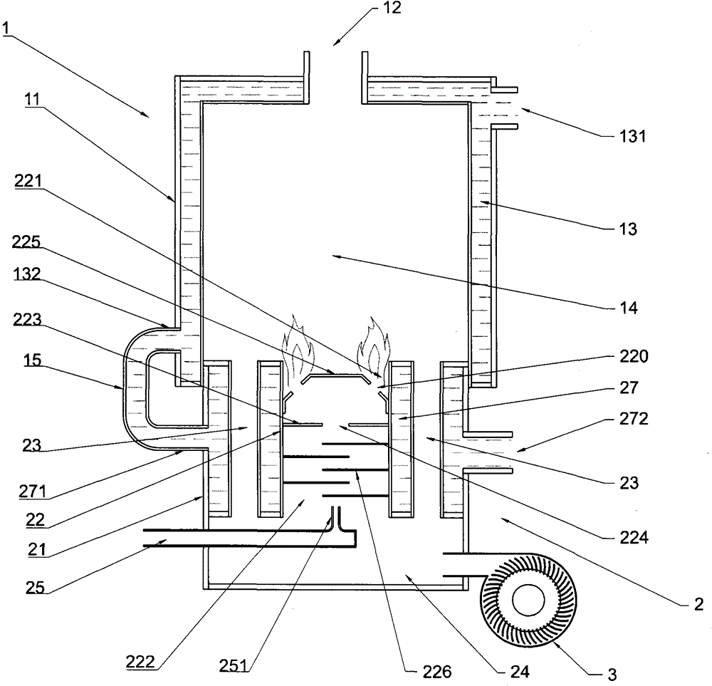
[0036] Such as figure 1 and figure 2 As shown, the gas boiler burner of the present invention includes a boiler body 1 and a burner body 2, and the two parts are arranged together to form the main structure of the present invention.

[0037] The boiler body 1 includes a boiler shell 11 in which a heating cavity 14 is formed. The boiler shell 11 is provided with a discharge port 12 , and the discharge port 12 communicates with the heating cavity 14 . In addition, the boiler shell 11 is provided with a first jacket 13, and the first jacket 13 is provided with a first water inlet 131 and a first water outlet 132, and the first water inlet 131 and the first outlet The nozzles 132 are all in airtight communication with the first jacket 13 .

[0038] The burner body 2 includes a burner housing 21, the upper part of the burner housing 21 is provided with a cylinder 22, the lower part of the burner housing 21 is formed with a first mixing chamber 24, and the upper part of the cylin...

Embodiment 2

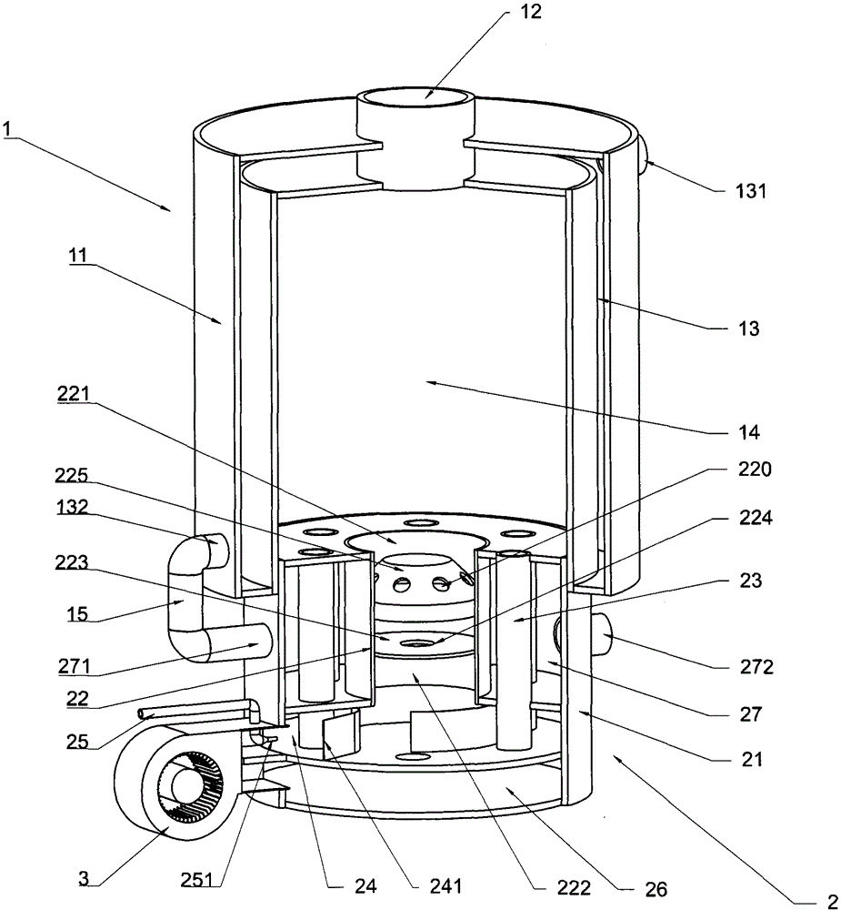
[0045] Such as image 3 and Figure 4 As shown, an air booster chamber 26 is provided below the first mixing chamber 24 of the present invention, and the air booster chamber 26 communicates with the air booster device 3 , and the lower end of the air channel 23 communicates with the air booster chamber 26 . Specifically for this embodiment, the first mixing chamber 24 and the air plenum 26 become independent chambers, the air plenum 26 provides air for the air channel 23 alone, and the first mixing chamber 24 becomes an independent chamber. At this time, the second mixing chamber 222 can be reserved or omitted. When omitted, the pressure-relieving partition 223 is arranged at the lower port of the cylinder 22, that is, the upper and lower sides of the slow-pressure partition 223 are respectively the combustion chamber 221 and the second mixing chamber. A mixing chamber 24, if the maximum amount of air flux in the barrel 22 is required, the pressure-relieving partition 223 is ...

Embodiment 3

[0048] Such as Figure 5 and Figure 6 As shown, a plurality of cylinders 22 are arranged side by side in the burner casing 21 of the present invention. Specifically in this embodiment, a plurality of cylinders 22 are evenly distributed in the burner housing 21, and each cylinder 22 is provided with several air passages 23 on the periphery, and the second jacket 27 surrounds all the cylinders 22; The combustion chamber 222 , the combustion plate 225 , the pressure relief partition 223 , the second mixing chamber 222 , and the second spoiler 226 are arranged in each cylinder 22 as in the first embodiment. The arrangement of multiple cylinders 22 in this embodiment enables the burner to output more balanced heat on a larger cross-section, and the gas pipeline of each cylinder 22 can also be controlled according to the demand for combustion heat.

[0049] The implementation manner and principles of other parts of this embodiment are the same as those of Embodiment 1 and Embodim...


PUM


Abstract

The invention relates to the technical field of burners, in particular to a gas boiler burner. The gas boiler burner comprises a boiler body and a burner body. The boiler body comprises a boiler shell. A heating cavity is formed in the boiler shell. The boiler shell is provided with a discharge port. The discharge port is communicated with the heating cavity. The burner body comprises a burner shell. A cylinder is arranged on the upper portion in the burner shell. A first mixing chamber is formed on the lower portion in the burner shell. A combustion chamber is arranged on the upper portion in the cylinder. A second mixing chamber is arranged on the lower portion in the cylinder. The combustion chamber is communicated with the heating cavity. A combustion plate with a plurality of combustion holes is arranged in the combustion chamber. A plurality of air passages are arranged in the cylinder or on the periphery of the cylinder. The first mixing chamber is connected with a gas pipe and an air boosting device. The burner shell and the boiler shell are connected with each other. The gas boiler burner has the advantages of being reasonable in structural arrangement, long in service life, more sufficient in combustion and the like.

Description

technical field [0001] The invention relates to the technical field of burners, in particular to a gas boiler burner. Background technique [0002] The gas boiler burner is a heating device using gas as the source material, which is well known and common. The general setting of existing boiler burners is: a gas nozzle, and an air nozzle is arranged near it, gas and air enter the combustion chamber together, mix and burn in the combustion chamber. The existing technology has the following defects and deficiencies due to the structural setting: 1. Because the gas is not fully mixed with the air, the combustion is insufficient, resulting in waste of resources; 2. The temperature around the flame port is high, and because there is no cooling system, after long-term use, It is easy to burn out, resulting in a short service life. Therefore, there is a large room for improvement in the current technology. Contents of the invention [0003] In order to effectively solve the def...

Claims


Application Information

Patent Timeline
Patent Type & Authority Patents(China)
IPC IPC(8): F23D14/02F23D14/64F23D14/78
Inventor 戴佩裕
Owner NINGBO DUOBEI MACHINERY IND
Why Eureka
Try Eureka