High-precision torque detection device

A torque detection, high-precision technology, applied in measuring devices, measuring torque/torsion force during tightening, calibration/testing of force/torque/power measuring instruments, etc., can solve chemical plant leakage explosions, wind turbine collapses, oil depots, etc. Leakage pollution and other issues to achieve the effect of ensuring stability and accuracy

Inactive Publication Date: 2014-11-05
KUNSHAN INNOVATION TESTING INSTR CO LTD +1
View PDF6 Cites 8 Cited by
  • Summary
  • Abstract
  • Description
  • Claims
  • Application Information

AI Technical Summary

Problems solved by technology

However, the torque setting of these torque tools or equipment is calculated theoretically by the manufacturer or calibrated by a foreign torque sensor. After being used in China for a period of time, it cannot be re-calibrated in China, resulting in failure of many key equipment in China. Torque connection failure...

Method used


Image

  • High-precision torque detection device
  • High-precision torque detection device
  • High-precision torque detection device

Examples


Embodiment 1

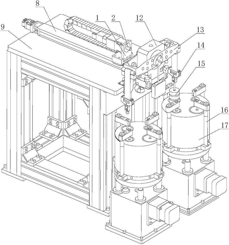
[0024] Such as Figure 1 to Figure 2 As shown, the first embodiment of the present invention provides a high-precision torque detection device, including a workbench 9, a guide rail seat 8, a weight fixing mechanism and a torque output mechanism, the guide rail seat 8 is fixedly arranged on the workbench 9, and the weight is fixed The mechanism includes a first fixing unit and a second fixing unit for fixing the two end faces of the tested product. The first fixing unit is fixedly arranged on the workbench 9 on the left side of the guide rail seat 8 in the length direction and is set between the guide rail seat 8 There is a gap, the second fixing unit is slidably arranged on the guide rail base 8 and slides back and forth along the length direction of the guide rail base 8, and the torque output mechanism is arranged under the first fixing unit.

[0025] In this embodiment, the first fixing unit and the second fixing unit fix the two end faces of the product to be tested to en...

Embodiment 2

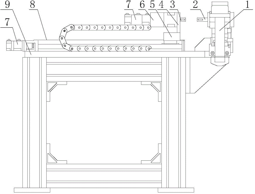
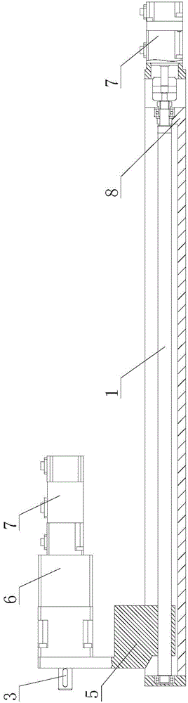
[0027] Such as Figure 3 to Figure 4 As shown, as the second preferred embodiment, the rest is the same as Embodiment 1, the difference is that the second fixing unit provided by this embodiment includes a slider 5, a second fixing frame 4 and a bracket for fixing the end face of the product under test. The second fixed shaft 3, the second fixed shaft 3 is arranged on the second fixed frame 4, the second fixed frame 4 is arranged on the slider 5, the slider 5 is slidably arranged on the ball screw 10, the second fixed shaft 3 and A motor 7 for driving the rotation of the second fixed shaft 3 is connected, and a reducer 6 is also arranged between the motor 7 and the second fixed shaft 3 .

[0028] The first fixing unit provided in this embodiment includes a first fixing frame 1, a first fixing shaft 2 and an air bearing 12 arranged on the first fixing frame 1. The first fixing frame 1 is fixedly arranged on the workbench 9. A fixed shaft 2 is arranged on the air bearing.

[0...


PUM

PropertyMeasurementUnit
Straightnessaaaaaaaaaa

Abstract

The invention relates to a high-precision torque detection device which comprises a working table, a guide rail base, a weight fixing mechanism and a torque output mechanism. The guide rail base is fixedly arranged on the working table. The weight fixing mechanism comprises a first fixing unit and a second fixing unit, the first fixing unit and the second fixing unit are used for fixing two end faces of a detected product, the first fixing unit is fixedly arranged on the working table and located on any side of the length direction of the guide rail base, a gap is formed between the first fixing unit and the guide rail base, the second fixing unit is arranged on the guide rail base in a sliding mode and slides back and forth in the length direction of the guide rail base, and the torque output mechanism is arranged below the first fixing unit. The first fixing unit and the second fixing unit of the high-precision torque detection device are used for fixing the two end faces of the detected product, so that fixation stability and measurement accuracy are guaranteed; the distance between the second fixing unit and the first fixing unit can be adjusted according to the length dimension of the detected product, and the high-precision torque detection device is applied to measuring products of different dimensions; the torque output mechanism is used for providing torque for the detected product, so that the torque is detected.

Description

technical field [0001] The invention belongs to the technical field of torque detection machinery, and in particular relates to a high-precision torque detection device. Background technique [0002] With the progress of society and the development of science and technology, people have higher and higher requirements for the safety performance of the items used in life. In order to ensure the safety of equipment operators, various industries have produced a variety of devices to test the safety of products. [0003] In today's industrial equipment, many equipment products, especially large-scale equipment and key parts of equipment, are connected by bolts and nuts for future repair and maintenance. For example: thermal power equipment, hydropower equipment, nuclear power equipment, wind turbine equipment, metallurgical equipment, mining equipment, shipbuilding equipment, petroleum and petrochemical equipment, etc. have tens of thousands of large bolts for the connection of t...

Claims


Application Information

Patent Timeline
IPC IPC(8): G01L5/24G01L25/00
Inventor 沈琪范海艇翁史煜姜鸣陶泽成
Owner KUNSHAN INNOVATION TESTING INSTR CO LTD
Why Eureka
Try Eureka